
|
|
Forum Index : Microcontroller and PC projects : Corrupted 1963 LCD display....
| Page 1 of 3 |
|||||
| Author | Message | ||||
Grogster Admin Group Joined: 31/12/2012 Location: New ZealandPosts: 9936 |
Hello folks.  Has anyone seen this problem before: 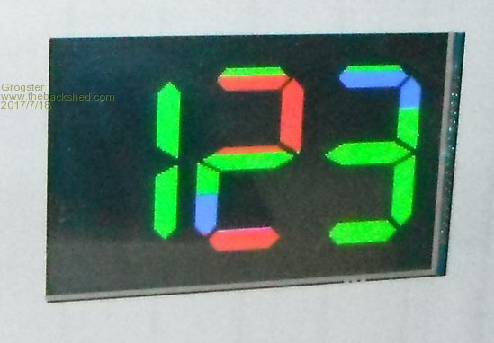 This happens on an E100, if I leave the PIC32 clock speed at 120MHz or 100MHz. As soon as I slow the CPU down to 80MHz or slower, the problem goes away. This LCD is set for 1963 backlight control, and at 100MHz or 120MHz, the backlight command has no effect at all, neither does CLS. Throttle-back to 80MHz, and everything works fine. I don't really care, so long as it works, but exactly how fast is the data clocked to the 1963 LCD's on the MM+ chips? It would appear to be affected by the clock speed, cos if you slow the clock right down, the LCD refresh rate is proportionally slower. Just curious...... matherp or Geoff? Smoke makes things work. When the smoke gets out, it stops! |
||||
| erbp Senior Member Joined: 03/05/2016 Location: AustraliaPosts: 195 |
Yes, similar at least. I have a 1963 display that won't work on an E100 if the CPU is running above 80MHz. 80 or below - no problems. From memory the issue I had was that it basically wouldn't display any text or graphics, and the background color would be something other than what I had set and was probably banded - i.e. bands of varying colors (been a while since I looked at it so some of the detail is a little hazy now). |
||||
| Grogster Admin Group Joined: 31/12/2012 Location: New ZealandPosts: 9936 |
Hi there. Yes, your description seems to be EXACTLY the same problem I am having here. Interestingly, I have NEVER seen this issue with 1963 7" LCD's, just the 5" ones, which is really confusing, as apart from a different LCD geometry, the controller chip is exactly the same SSD1963 in both types....  Oh well. I don't really care so long as it works by throttling back a little, but it is curious. I tried running the PIC32 at 5MHz just for a giggle - boy, that makes for a slow refresh rate!  Smoke makes things work. When the smoke gets out, it stops! |
||||
| matherp Guru Joined: 11/12/2012 Location: United KingdomPosts: 11224 |
The effect is caused by the display missing a WR pulse. Then the colours get out of sequence as there are three 8-bit transfers per pixel. Check all the usual H/W errors: dry joint, noisy power etc. |
||||
| Grogster Admin Group Joined: 31/12/2012 Location: New ZealandPosts: 9936 |
Okey dokey - thanks for the pointer. Will do. I have two separate E100 boards, and two separate LCD's. BOTH of them won't behave at >80Mhz, and BOTH of them will if <=80Mhz. It is very handy to know it is related to the WR pin, so I will investigate a little more. I guess not all LCD's are equal in the eBay and AliExpress world..... Smoke makes things work. When the smoke gets out, it stops! |
||||
| matherp Guru Joined: 11/12/2012 Location: United KingdomPosts: 11224 |
The 5V displays are powered through a single pin at 3.3V whereas the 7" displays have a separate 5V supply for the backlight. Can't find my E100 to check but you really need a beefy connection and good decoupling/bulk capacitance to the power pin for the 5" display. On one of my 5" displays I cut the track to the backlight boost circuit and powered it from 5V. It is the track on the outer end of C21 |
||||
jman Guru Joined: 12/06/2011 Location: New ZealandPosts: 711 |
I have been struggling with a corrupt 5" display for ages the "effect" is worse when loading bmp images and thanks to this thread and Peters 5V mod the issue now 99% resolved. I will add some caps and hopefully this sort the last 1% Regards Jman |
||||
| Grogster Admin Group Joined: 31/12/2012 Location: New ZealandPosts: 9936 |
Yes, thanks from me too - I will make the mod at my end and see if it fixes my issues as well. EDIT: Is this how you do it? I want to be sure before I blow up a perfectly good LCD.... 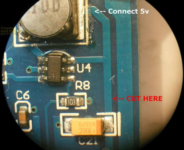 Smoke makes things work. When the smoke gets out, it stops! |
||||
| matherp Guru Joined: 11/12/2012 Location: United KingdomPosts: 11224 |
I cut the other side of C21 to leave it in circuit. It is easy to go back to normal if required by soldering a link across the cut |
||||
| Phil23 Guru Joined: 27/03/2016 Location: AustraliaPosts: 1667 |
Hi Grog, Been meaning to make this post, but haven't got there till now. I have 2 E100 with 5" displays which are fine. BUT A friend bought an E100 a few months back & has screen issues. He bought a second display & still has issues. His displays appear to fail on my E100's also when we test them. His email to me.... Photos added below, their context in his quote. [Quote=RF]Some examples of display failure when using TAB 4 of Phil's code This usually happens within 10 to 15 minutes In this case the screen registration is down half a line In this case the colours have changed. Also we quite often get flickering incorrect chars on the screen. This was on Phil's hardware using two separate screens. Both these screens appear to be slightly different to Phil's screens (which work fine) Any clues or ideas appreciated. I bought the second screen when the first screen gave trouble. So I now potentially have two bad screens (or two slightly different screens) . They seem fine until they are pushed by the high update rate of Phil's TAB 4. Thanks in advance[/quote] All these examples are RF's displays on my E100. The last image shows the part number on the ribbon cable which is different to mine. Both mine have V2 in the number near the end, but I don't have them on hand. Phil. 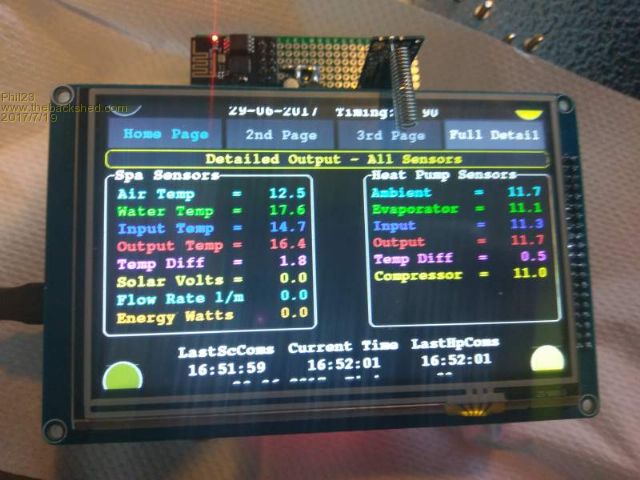 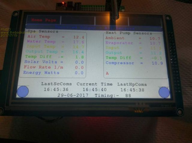 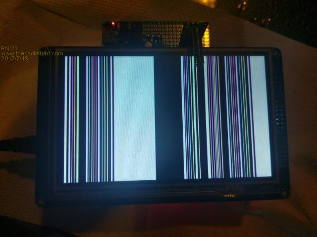 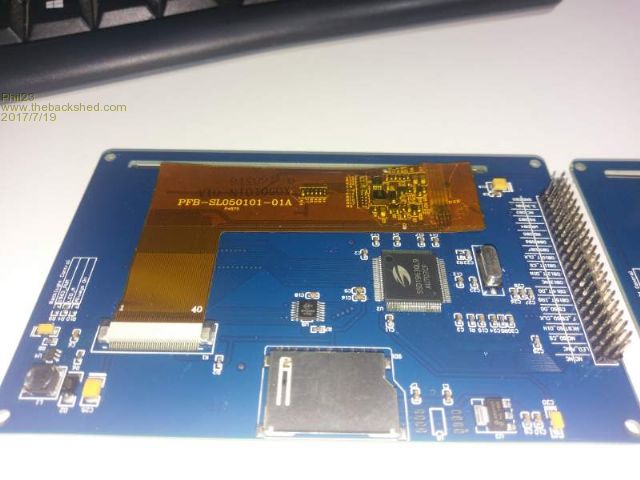 |
||||
| Grogster Admin Group Joined: 31/12/2012 Location: New ZealandPosts: 9936 |
I have mainly the 2A LCD's, but I also have 01A LCD(I've just looked), so I will plug the 01A into a working E100 and see if I get the same result. I don't think it should matter, as that number is only for the LCD matrix thing-y, the 1963 controller chip is the same across all these displays, so they should ALL work in an ideal world. Please ask them to SLOW DOWN the CPU to no more then 80MHz just to see if the problem clears, also do the 5v mod that matherp recommends to see if that helps. I will post back here with the results of my testing on the different LCD. [Quote=Phil]His displays appear to fail on my E100's also when we test them.[/Quote] This suggests that the LCD does not like something. It also suggests that the problem is definitely with the LCD, NOT the E100, as if the LCD was fine, then it would spring to life on your E100 which is known to be good. Smoke makes things work. When the smoke gets out, it stops! |
||||
| jman Guru Joined: 12/06/2011 Location: New ZealandPosts: 711 |
Hi After doing the 5V mod and adding some caps the display still got corrupted but not nearly as bad (99% good) setting the CPU speed to 80Mhz has completely cured it. Regards Jman |
||||
| Grogster Admin Group Joined: 31/12/2012 Location: New ZealandPosts: 9936 |
Progress then. EDIT: I have tried the 01A LCD, and I can't fault that one - even at 100MHz. For me, it was the V2 LCD's that would not behave at 100MHz, but are fine at 80MHz. Smoke makes things work. When the smoke gets out, it stops! |
||||
| Phil23 Guru Joined: 27/03/2016 Location: AustraliaPosts: 1667 |
|
||||
| MicroBlocks Guru Joined: 12/05/2012 Location: ThailandPosts: 2209 |
It probably is the pulse width of the write signal. At 100Mhz those will be very short and have to be very clean transitions. Maybe put a scope on this signal and examine it. Maybe the rise or fall edges are not that sharp on those speeds. Cables, capacitance/resistance of the traces if they are long, etc Can have lots of causes. Microblocks. Build with logic. |
||||
| KeepIS Guru Joined: 13/10/2014 Location: AustraliaPosts: 2108 |
Just got my 5" and 7" displays, fortunately I plugged the 7" in first and had it going in a few seconds (had all the commands ready). Reset and plugged in the 5", tried to get it to go, incorrect characters displayed from the PS2 keyboard, could not use EDIT command as the Cursor was on the RH side of the screen, CLS would not do anything but remove a thin vertical strip in the middled of the screen, GUI TEST ran ok. I thought I had a dud 5" panel (It had been worked on by the look of it) Thankfully I found the thread - many thanks - dropped it back to 80Mhz and it worked. Will try the 5V mod when I get a chance - love the 7". NANO:Inverter V 8.2ks - Linux AvrDude GUI script V4.1 |
||||
| robert.rozee Guru Joined: 31/12/2012 Location: New ZealandPosts: 2503 |
would it to be silly to suggest extending the write pulse in the firmware?! the odd nop instruction can do wonders in such cases. cheers, rob :-) |
||||
| Grogster Admin Group Joined: 31/12/2012 Location: New ZealandPosts: 9936 |
Interesting. When the original 5"/7" LCD drivers were being written, there was no evidence of this problem that I can remember. matherp did mention earlier that the reason for this corruption, is a missing WR pulse. Could it simply be a case of certain SSD1963's clock speed being a little slower on some boards, and the WR pulses are just too fast for the display in those circumstances? Having said that, dropping the CPU speed to 80MHz always seems to fix the issue, which perhaps suggests that different batches of SSD1963 LCD can be different enough to NOT see the WR pulses depending on what LCD you happen to get. Smoke makes things work. When the smoke gets out, it stops! |
||||
| matherp Guru Joined: 11/12/2012 Location: United KingdomPosts: 11224 |
Things are not as simple as you may think The PIC32MX has a divider that scales the I/O clock relative to the system clock. Bizarrely, 80Mhz is the fastest CPU speed at which the divider is set at 1:1. Above 80MHz the clock is set to 1:2 So the I/O is actually slower at 100/120MHz than it is at 80MHz. For reference the divider on the MZ is 1:2 at 200MHz and 1:3 at 252MHz. However, in both cases I have one NOP before and after each edge of the WR pulse |
||||
| robert.rozee Guru Joined: 31/12/2012 Location: New ZealandPosts: 2503 |
|
||||
| Page 1 of 3 |
|||||
| The Back Shed's forum code is written, and hosted, in Australia. | © JAQ Software 2026 |
