
|
|
Forum Index : Microcontroller and PC projects : HC12 @ 3v3...
| Author | Message | ||||
Grogster Admin Group Joined: 31/12/2012 Location: New ZealandPosts: 9931 |
Hello everyone.  Can anyone here state if they use the HC12 module at 3v3 with no problems? Datasheet says Vcc can be 3.2v-5.5v, so I normally always go for 5v, simply cos running them at 3v3 is only 0.1v above their minimum rating. However, running them at 3v3 would make life easier for me, as then the MM and the HC12 are both running at the same voltage, so I can simplify the PCB and only use one regulator instead of two as I use now. Can anyone confirm with any degree of certainty that they run OK on 3v3? I do intend to run some of my own tests at this voltage anyway, but I am interested in anyone who may have their own thoughts to add to the think-pile at this point in time. Smoke makes things work. When the smoke gets out, it stops! |
||||
| Phil23 Guru Joined: 27/03/2016 Location: AustraliaPosts: 1667 |
Hi Grog, I originally ran mine on 3.3 on one of my backpacks. Couple of months from memory. All was fine for a while, but then started having issues that turned out to be voltage losses on a solder less proto board. Found the module was only getting around 3. Added a few more wires & it was Ok again, but ended up with it on 5V as the bread board I was testing on was too poor when it came to voltage loss. Based on that I presumed 3.3 would have been fine on a properly made board. Cheers Phil. |
||||
| Grogster Admin Group Joined: 31/12/2012 Location: New ZealandPosts: 9931 |
Interesting, thanks Phil. Still interested in any other members' thoughts. I can stick with the 5v regulator no problems, I am just looking at ways to simplify the design if possible. Smoke makes things work. When the smoke gets out, it stops! |
||||
| Alastair Senior Member Joined: 03/04/2017 Location: AustraliaPosts: 161 |
G, Recently I built a prototype to log all the temps on my solar hw and then update a base unit via hc-12. The logging end uses an E28 from across the pond  and I thought it would be best to just run everything from 3.3v. I varied the supply voltage on the HC-12 from 3 to 5v whilst watching the behaviour on the scope and a continuous transmission test program. The HC-12 started working at around 3v but I was getting a few errors according to my checksum routine. From about 3.3 v it all worked perfectly. and I thought it would be best to just run everything from 3.3v. I varied the supply voltage on the HC-12 from 3 to 5v whilst watching the behaviour on the scope and a continuous transmission test program. The HC-12 started working at around 3v but I was getting a few errors according to my checksum routine. From about 3.3 v it all worked perfectly.I decided on the basis of this limited test that it was too close to the margin at 3.3v and went with 5v. I did not vary the distance beyond the 10m through 2 walls and I only tested one HC-12. Not rigorous. Not quite what you want but some info. The final version is running happily. The waterproof ultrasonic transducer for the rainwater tank level sensor arrived the other day so I have to add that in - hopefully the connector I put in will just allow me to plug and go. Cheers, Alastair |
||||
| Grogster Admin Group Joined: 31/12/2012 Location: New ZealandPosts: 9931 |
Thanks Alastair. No, this IS kinda what I expected to have most people say. I think that 5v is the standard operating voltage for HC12's, but.... I think I will just continue to use them at 5v. We are only talking a 60c regulator anyway. Smoke makes things work. When the smoke gets out, it stops! |
||||
| Andrew_G Guru Joined: 18/10/2016 Location: AustraliaPosts: 874 |
Hi Grogs, In this post I raised my need to conserve power to a remote temperature sensor powered by two AA batteries (ie 3.2V). It is still working (just) with the batteries down to 2.93V. The jiffy box (~ 8 x 5 x 3mm) contains 2x AA, MM170, DS18B20 and HC-12. It is running in FU2 mode at 2400 baud and is only sending temperature every 10 minutes - it is meant to be asleep in between. It is only having to transmit say 20m but through 5 brick walls. If my rat's nest can work at 2.93V I'd reckon 3.3 would be OK (but it might depend on range etc.). Please keep us posted as I'm keen to improve on my rat's nest. Cheers, Andrew |
||||
| Alastair Senior Member Joined: 03/04/2017 Location: AustraliaPosts: 161 |
I have another project on the list which involves sending data back to the base. This time it is a bit further and from our truck based 'expedition vehicle'. It sits parked too much and I want to be able to check the status of things easily. Yes I know - lazy. Battery consumption is not an issue -320AH LiFePO4 with 600w panels - the system is all electric - hw, induction cooktop etc. I have just received my pcbs back from Elecrow so I will be starting the monitor system in a weeks or so. I will use it as an excuse to do a more rigorous test of the HC-12 and set it up to run at 3.3v unless it proves unreliable. Don't hold breath - weeks before it is finished and installed. Wife has project list too !! Cheers, Alastair |
||||
| matherp Guru Joined: 11/12/2012 Location: United KingdomPosts: 11144 |
Remember you can run the MM at up to 3.6v to get more headroom |
||||
| Alastair Senior Member Joined: 03/04/2017 Location: AustraliaPosts: 161 |
Matherp, Thanks. I did not know that. I had thought that 3.3v was a hard maximum. Having the extra 0.3v would probably make a significant difference to the hc-12. I will (eventually) check it out. cheers Cheers, Alastair |
||||
| Pluto Guru Joined: 09/06/2017 Location: FinlandPosts: 411 |
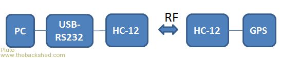 I made this test a couple of months ago: GPS and the right-side HC-12 were powered by 3.3V, while the left side HC12 got power (5V) from the USB-RS232 (CP2102). Walked around the block with the GPS&HC-12 unit, which transmitted the GPS messages to the PC. The GPS data received were then plotted on the map by the software found at http://www.hamstermap.com/quickmap.php In this way I could easily see how far the HC-12 communication worked. (A few hundred meters when not too many houses between TX and RX. Only small spring antennas on the HC-12 units.) Found out later that it would have been even easier with Ublox u-center software, which plots GPS data directly on Google Map. The original reason for making the setup with HC-12 was that the logic signals directly from the GPS-unit were not recognized by any terminal programs in my PC. Picoscope did however recognize and decode the GPS messages correctly. The trick with two HC-12 worked well. In fact it was a "wireless level translator" for 3.3V TTL to 5V TTL. I did not see any issues by operating at 3.3V. The HC-12 on-board processor is specified down to 2.95V and the RF-chip Si4463 down to 1.8V. TX power will however be reduced if the voltage decreases. The difference between 3.3V (+20dBm) and 3.0V (+19dBm) is about 1dBm. |
||||
| Grogster Admin Group Joined: 31/12/2012 Location: New ZealandPosts: 9931 |
Hello Pluto - welcome to the forums. That is good information to have - thank you. I think the issue is not so much the fact that the ST processor can run down at 2.95v and the 4463 can run down to 1.8v, as much as the fact that the on-board LDO will drop off completely at around 3.1v or so, and as the LDO supplies both chips.....  I have been running some tests at 3v3, and have not had any issues so far. In my application, I only EVER want to use the HC12 as a receiving node, and NEVER a transmitting one, so I think I will be safe enough, so long as it will run at all at 3v3 - which it seems to be doing happily enough. Smoke makes things work. When the smoke gets out, it stops! |
||||
| Pluto Guru Joined: 09/06/2017 Location: FinlandPosts: 411 |
Thanks Grogster. have you tried to bypass the LDO? That could be a solution if you would like to operate at lower voltage. |
||||
| Grogster Admin Group Joined: 31/12/2012 Location: New ZealandPosts: 9931 |
[Quote=Pluto]Thanks Grogster. have you tried to bypass the LDO? That could be a solution if you would like to operate at lower voltage.[/Quote] Yes, I guess I could do that if I was desperate. Desperation has not set in just yet though. Smoke makes things work. When the smoke gets out, it stops! |
||||
| The Back Shed's forum code is written, and hosted, in Australia. | © JAQ Software 2026 |
