
|
|
Forum Index : PCB Manufacturing : AutoTRAX DEX Tips and ideas
| Page 1 of 2 |
|||||
| Author | Message | ||||
bigmik Guru Joined: 20/06/2011 Location: AustraliaPosts: 2981 |
Hi All, I hope that this will be a very long thread with ideas and tips to make your experience with DEX a bit more pleasing. I recently discovered on the Dex Forum User MiR posted a PIC32MX170 SOIC part and he incorporated an IMAGE into the schematic which IMHO made the Schematic look much better.. See this example. He provided 2 parts with slightly different images. 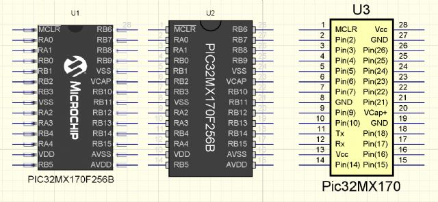
This is two images of the same part next to my standard PIC32MX170 - SSOP The parts themselves are attached here: 2016-06-02_071026_PIC32MX170B_With_Images.zip Regards, Mick EDIT *** The images got compressed by TBS so I have attached them in this ZIP 2016-06-02_071429_PICs.zip Mik Mick's uMite Stuff can be found >>> HERE (Kindly hosted by Dontronics) <<< |
||||
lew247 Guru Joined: 23/12/2015 Location: United KingdomPosts: 1709 |
I haven't played with Dex yet, I'm waiting till I finish the project I started months ago. Those images look really nice, and I'm looking forward to trying it properly, it didn't take long to learn Diptrace, hopefully it will be the same with Dex |
||||
| bigmik Guru Joined: 20/06/2011 Location: AustraliaPosts: 2981 |
No Worries Lew, Hope you have a successful trip with AutoTRAX DEX. Have a read of my tutorial located in This Thread Note! The Manual is how `I' go about creating a board.. You may decide to do things differently than me. Kind Regards, Mick Mick's uMite Stuff can be found >>> HERE (Kindly hosted by Dontronics) <<< |
||||
plover Guru Joined: 18/04/2013 Location: AustraliaPosts: 306 |
I have managed to follow your manual and got your headers onto a pcb and viewed this in 3D. The 3D is impressive, I thought I had left pcb work behind, but not just yet now. It ocurred to me that headers shown in schematic does not show visual male/female nor right/left description. I can visualise the straight headers showing male with a dot per pin inside the rectangular outline. I do not know enough to edit a part to show example yet. Similar for female a circle per pin inside the rectangular area. Right angle headers, hmmmm do not have an instant idea desriptor.  |
||||
| bigmik Guru Joined: 20/06/2011 Location: AustraliaPosts: 2981 |
Hi All, Another useful TIP. On the HOME menu there is a button called RECOVER 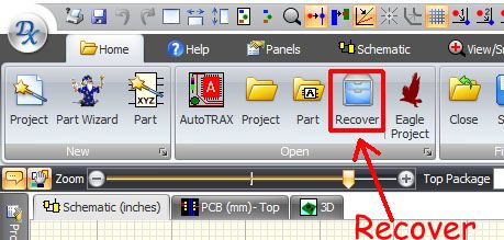
This will bring up a list of all of the automatic system saves (DEX saves EVERY change you do to your project) for those times where you have done something wrong and just can't see an easy way to fix it.. Just browse your recent saves and revert back to an earlier time where you were happy with your project. Don't worry if you realise you have gone back too far your `later' saves are still there.. By clicking Restore you get a pop up that allows you to click on the PCB or Schematic to get a preview of the project before clicking the Restore button (at the bottom of the panel) to bring up your earlier version. 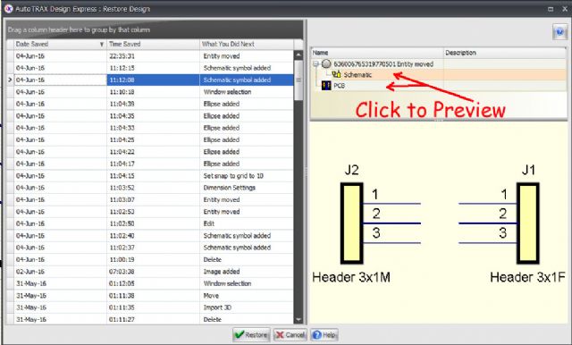
NOTE! Currently the save time appears to show GMT times and not local times.. I have reported this to Iliya and hopefully that will be addressed soon. Kind Regards, Mick Mick's uMite Stuff can be found >>> HERE (Kindly hosted by Dontronics) <<< |
||||
| bigmik Guru Joined: 20/06/2011 Location: AustraliaPosts: 2981 |
Hi Plover, Yes you can add any symbols that you like in your parts.. The following is just adding a few dots (solid for Male and hollow for Female) 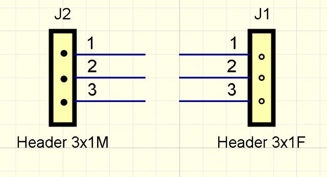
Of course with the ADD-IMAGE facility you can add whatever image you like. 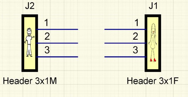
These are all done with the ADD key tab.. I used the Solid circle for the male, hollow circle for the female and Image for the mini pictures. 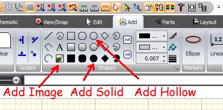
Kind Regards, Mick Mick's uMite Stuff can be found >>> HERE (Kindly hosted by Dontronics) <<< |
||||
| bigmik Guru Joined: 20/06/2011 Location: AustraliaPosts: 2981 |
Another TIP, By expanding the WIRES tab (bottom right hand corner) in the Schematic tool bar you can bring up a list of property options for wires and jumpers. 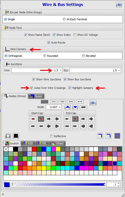
I selected ROUND wire corners, Jump over wire crossings and Highlight jumpers and my schematic now looks like this. 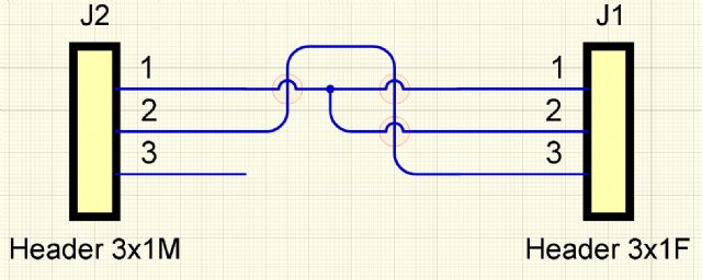
TBS compresses the images so I suggest you have a play and see what you prefer for your wires. You can also set the `global' wire/node colours, wire widths and other styles Kind Regards, Mick Mick's uMite Stuff can be found >>> HERE (Kindly hosted by Dontronics) <<< |
||||
| bigmik Guru Joined: 20/06/2011 Location: AustraliaPosts: 2981 |
Hi Plover, Hold Ctrl down and the elipse snaps to a circle. Once your circle is drawn just drag it to the location you want, experiment with the snap grid settings on the top (middle) tool bar. 
Also if you want you can change the colour of the outline and the inner fill by clicking on the boxes just to the right of the shapes menu.. currently it is set for BLACK outline and GREY fill. Of course if you load a part and edit it to put what ever marker you chose you can then save that part away and it will bring in your markings with it. Kind Regards, Mick Mick's uMite Stuff can be found >>> HERE (Kindly hosted by Dontronics) <<< |
||||
| bigmik Guru Joined: 20/06/2011 Location: AustraliaPosts: 2981 |
Hey Plover, Did you delete your message whilst I was replying or have I gone Mad in the last few minutes? 
Kind Regards, Mick Mick's uMite Stuff can be found >>> HERE (Kindly hosted by Dontronics) <<< |
||||
| bigmik Guru Joined: 20/06/2011 Location: AustraliaPosts: 2981 |
Another TIP I have found useful, DEX normally shows all the layers viewed from the TOP so when you add text to the bottom silkscreen it will look something like this: 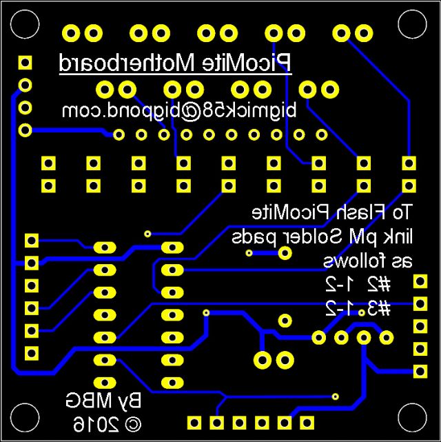
Now whilst you can work out what it says it isn't quite the same as seeing the board (of course you can view the 3D and see it) but there is a little icon hidden away on the right hand side of the PCB key tab called `View From' that will allow you to view from the BOTTOM side of the board.. 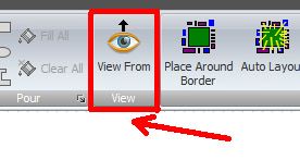
This will reveal something like this. 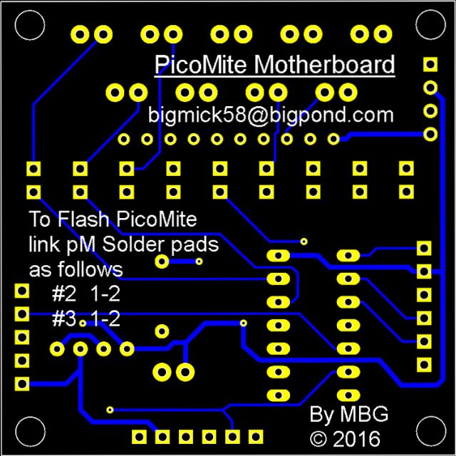
Yes this is one of my latest two boards, currently in production, I will have in approximately one month. There are 2 boards in this order and the first person to PM me with a decent description of what the two are will get one of each including shipping anywhere in the world. (Note I am looking more than a name I am after a brief description of what they are for, or what they do) Hint Have a look at my `site' HERE and look at two very similar boards. Note they will be at least a month before I have them available.. (I ordered slow boat from China shipping) Kind Regards, Mick Mick's uMite Stuff can be found >>> HERE (Kindly hosted by Dontronics) <<< |
||||
| MicroBlocks Guru Joined: 12/05/2012 Location: ThailandPosts: 2209 |
One board (PicoMite) will be an 'adapter' for an SMD PIC chip that fits a 14 pin DIP socket and can be easily programmed on the PicoMite motherboard. Also testing it by using some jumpers and leds to check if it is functional. Am i close? Microblocks. Build with logic. |
||||
| bigmik Guru Joined: 20/06/2011 Location: AustraliaPosts: 2981 |
Ahhh Jean, You got it.. When they arrive ONE set is yours.. Kind Regards, Mick Mick's uMite Stuff can be found >>> HERE (Kindly hosted by Dontronics) <<< |
||||
| MicroBlocks Guru Joined: 12/05/2012 Location: ThailandPosts: 2209 |
I just now realize that i should have send that with a PM. I am dumb sometimes, sorry for that. [pushing my own agenda a bit] The concept is nice, but ..... it is missing my USB-Serial-PIC32 programmer chip, then you would not even need a pickit3 and MPLab IPE to program the chip. :)
If you design a board with it you get the hex file for free, as i made that deal with several other users of this forum. [/pushing my own agenda a bit] I am getting used to DEX and this is my progress of the little board. Still not good at it as it takes way to much time but slowly getting there. Here is my v2 of the USB-Serial-Programmer as a little module that measures 17.78x12.7mm and has castellated holes that are on a 0.1" grid. No idea yet if that will be manufacturable by our friends in Shenzhen. 
And i moved to another place, so don't send them to my old address. They will have no clue what to do with them. :) Microblocks. Build with logic. |
||||
| bigmik Guru Joined: 20/06/2011 Location: AustraliaPosts: 2981 |
Hi Jean, I was going to disqualify you but I felt pity (or fear) so I let it slide. The reason for PM was to keep the forum clean, Whilst I like your chip I have a standard that I like to support (the 6 pin header for the USB cable) but I will bear your suggestion in mind for future and the designs there were both a rework of the existing NanoMite ones. Sorry there were no pictures in your post can you either email them to me os post them again. Kind Regards, Mick Mick's uMite Stuff can be found >>> HERE (Kindly hosted by Dontronics) <<< |
||||
| bigmik Guru Joined: 20/06/2011 Location: AustraliaPosts: 2981 |
Hi Jean, You might be pleased to know that I have just about finished MuP Version 3, that includes your fantastic USB-TTL/Programmer chip. 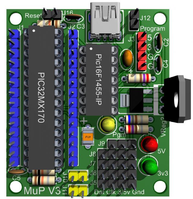
Whilst MuP2 was `almost' entirely Through Hole plated (just the VCap needed to be SMD) I have designed MuP 3 to be, optioned by the builder, to entirely THP if they wished or they can use the SMD VCap and/or SMD version of the Regulator.. The SMD VReg and TO-220 VReg are self exclusive, they can be one or the other.. NOT BOTH. Same for the VCap, it can be SMD or THP via the holes provided. The beauty is that there is no need for the ICSP header as your chip will handle any flashing of new MMBasic versions without the need for a PicKit3 or similar. Anyway MuP Ver 3 will be sent off for manufacture this week sometime. Kind Regards, Mick Mick's uMite Stuff can be found >>> HERE (Kindly hosted by Dontronics) <<< |
||||
| MicroBlocks Guru Joined: 12/05/2012 Location: ThailandPosts: 2209 |
Hi Mick, Yes i am pleased. :) It is for me a confirmation that i am on the right track. Always difficult to find a little niche. Thanks for using it and i hope the ones who use your MuP - (i have a few of the v1's and they are great to use) - also find it an easy way to work with the uMite. Not many through hole products/kits around anymore so that is by itself also an achievement. Microblocks. Build with logic. |
||||
| isochronic Guru Joined: 21/01/2012 Location: AustraliaPosts: 689 |
looks pretty good ! And will run other software OK too :) How soon to arrival ?? BTW I think this section should be the place for new pcb's, but they are hidden unless they get new headings |
||||
| isochronic Guru Joined: 21/01/2012 Location: AustraliaPosts: 689 |
I think MB's programmer would fit into the colour maximite case ? That would mean people could upgrade the CM firmware easily |
||||
| bigmik Guru Joined: 20/06/2011 Location: AustraliaPosts: 2981 |
Hi Chronic, All, I have modified MuP V3 to add an SPI header in the area that currently says MuP V3 it has the 3 SPI pins as well as Gnd and Pin(15) for a chip select.. I wont clutter this thread as I will publish it when the boards arrive and they test OK. TIP Now to stay with the theme of TIPS I offer this one. In the 3D view, if you want to capture the board as it is shown on the screen without all of the background blue shades press Ctrl-C to copy the board ONLY to the clipboard.. Then just paste into your picture editor. Kind Regards, Mick Mick's uMite Stuff can be found >>> HERE (Kindly hosted by Dontronics) <<< |
||||
| plover Guru Joined: 18/04/2013 Location: AustraliaPosts: 306 |
bigmik Not sure how I landed in this thread this time, I take it as an omen. MicroBlocks a few posts above, Posted: 17 June 2016 at 2:07pm seems to have attached a picture I guess but it will not display here as it says there is an error. Did you ever get a copy of that, it is 2 years ago but just in case I am asking as I am interested in seeing the castellated edges on a small circuit. p. |
||||
| Page 1 of 2 |
|||||
| The Back Shed's forum code is written, and hosted, in Australia. | © JAQ Software 2026 |
