
|
|
Forum Index : PCB Manufacturing : Pi-backpack
| Page 1 of 2 |
|||||
| Author | Message | ||||
| led-bloon Senior Member Joined: 21/12/2014 Location: AustraliaPosts: 209 |
Any volunteers for an ILI9341 backpack for the RaspberryPi. A SIMPLE board with some headers for the Pi, the display/touch AND the SD card slot (maybe SPI & I2C connections too?). The 2.8" display fits nicely over the standard sized Pi although insulation needed at the USB connector cans. The SD card for removal of log/data files on-the-fly. I've got DEX but too exhausting - overpowering - even for something this simple! Miss you George |
||||
Grogster Admin Group Joined: 31/12/2012 Location: New ZealandPosts: 9910 |
Doesn't the Pi-cromite use the Pi's own SD card slot for access to programs? I could whip up something in a day or five. I think that the 2.8" LCD is a good choice. I will look into this a little more, if no-one else has plans to do the same thing. Smoke makes things work. When the smoke gets out, it stops! |
||||
| led-bloon Senior Member Joined: 21/12/2014 Location: AustraliaPosts: 209 |
Grogster The display SD card for removal/changing of log/data/picture files while the unit is running. However, as you say, any of these types of files could be written/read off the Pi SD card using ftp or other unix file transfers I guess, as long as you have network access! The pcb should probably have mounting/spacer holes for the Pi zero (W) board as well as the full size Pi. Access to SPI, I2C & other spare GPIO an advantage. Thood for fought? don Miss you George |
||||
| Grogster Admin Group Joined: 31/12/2012 Location: New ZealandPosts: 9910 |
Critical thing to know at this point, is if the Pi-cromite actually even supports an SD card as you would find on the LCD module. I expect that matherp wrote the Pi version of MMBASIC to ONLY look at the Pi's SD card, is what I am getting at.  Peter - if you are reading this, perhaps you could clarify please. I need to do a little refresher on the Pi version of MMBASIC to find out. EDIT: I have just read through all 18 pages of the Pi-cromite thread, but nowhere in that thread, does matherp mention support of a 2nd SD card, so I therefore fully expect that the only SD card supported, is the on on the PI. Smoke makes things work. When the smoke gets out, it stops! |
||||
| led-bloon Senior Member Joined: 21/12/2014 Location: AustraliaPosts: 209 |
OK, fair enough. One last thought. Being SPI driven, the full SD card support could be added. It's easier to add code later, a bit trickier adding traces to pins later though. Miss you George |
||||
| Grogster Admin Group Joined: 31/12/2012 Location: New ZealandPosts: 9910 |
You have a point. An excellent point, actually. I will see if I can rustle something up soon, and will incorporate the SD card on the LCD, but the CS pin is an unknown, so you would have to add a small wire jumper later - if this was ever supported. Smoke makes things work. When the smoke gets out, it stops! |
||||
| led-bloon Senior Member Joined: 21/12/2014 Location: AustraliaPosts: 209 |
You actually will need 3 x CS, Reset, D/E & T_IRQ all of which are user programmable. I think you just assign 6 pins yourself (pick a number) and just run with that! You obviously would not pick pins 3,5,7 as they are I2C and Peter has assigned certain other pins for functions, so will have to check these out first. The Backlight I would run with a fixed resister or a pot. Miss you George |
||||
| led-bloon Senior Member Joined: 21/12/2014 Location: AustraliaPosts: 209 |
Have scanned all of Peter's threads for the Pi-cromite and have come up with the following pin list as documented: SPI : Pins 19, 21, 23 I2C : Any pins can be used! User configurable (3 & 5 pi default pins). SETPIN CIN, PIN, and FIN : pins 11,13,15 & 16 PWM or SERVO : Any pin can be used! Pin 12 is the hardware PWM (1Hz - 25MHz) All other pins based on a 1uS clock so frequencies will be exact divisors of 1,000,000. More info for PWM & SERVO at: http://www.thebackshed.com/forum/forum_posts.asp?TID=9487&PN=1&TPN=6 IR Send/Receive : Pin 16 for receive. Any pin can be used for transmit! COM1 : Tx pin 8, Rx pin 10 COM2 : Tx pin 7, Rx pin 11 -------------------------------------------------------------------------------- Displays supported: ILI9341 (320x240), ILI9163 (128x128), ST7735 (128x160) & ILI9481 (480x320) ILI9341: Display using SPI (CS, D/C & Reset configurable) Touch using SPI (CS & IRQ configurable) SD card using SPI (CS configurable) SSD1963: RD (optional transparent text & BLIT) user configurable WR pin 32 RS pin 13 RESET pin 31 DAT1 pin 35 DAT2 pin 38 DAT3 pin 40 DAT4 pin 15 DAT5 pin 16 DAT6 pin 18 DAT7 pin 22 DAT8 pin 37 Information for anyone interested edit: Correction one pin deleted from list Miss you George |
||||
| Phil23 Guru Joined: 27/03/2016 Location: AustraliaPosts: 1667 |
Sounds pretty minimal, but not is my list of doables; ZERO PCB design experience. Have you considered Routaboard or Perfy ? Both have some software to play about with & ATM I'm looking at adding an IO board to the CGM2 MM+. Actually have some Perfy on hand, lightning fast delivery, but at the time we ordered It I didn't realise there was a double sided variant of Routaboard. It looks very flexible with 2 horizontal trace tracs per pin on the reverse side. Phil. |
||||
| Grogster Admin Group Joined: 31/12/2012 Location: New ZealandPosts: 9910 |
This is on my to-do pile, but things have been busy lately. I will have a go at this soon. The compiled list led-bloon did above is very useful, and will save me a whole heap of thread reading, so that helps. Smoke makes things work. When the smoke gets out, it stops! |
||||
| Grogster Admin Group Joined: 31/12/2012 Location: New ZealandPosts: 9910 |
I've been playing with this idea a little tonight. I have designed a Pi-zero and a standard PI footprint, and have been playing with these along with LCD footprints. The standard PI might need to be dropped on this backpack board idea. The PI-Zero fits beautifully with a 2.8" SPI LCD, on a board of the same size as the 2.8" LCD. The standard-size PI is too big to fit as a piggy-back arrangement with any LCD smaller then 4" or so. The Pi-Zero is a perfect match though, as it is small and SO CHEAP, that this makes it the most logical choice - for SPI LCD's. The PI-Zero and a 2.8" SPI LCD give you a complete system with touch and advanced GUI controls for fifteen bucks or so, which is very impressive. So, at this stage, I am dropping off the standard-size PI footprint, and the piggy-back board will concentrate on the PI-zero module. I am designing for either a 2.8" LCD with ILI9341, or a 3.2" LCD with SSD1963 - you can use either type on the same board(but not together). EDIT: Seems there is no 3.2" SSD1963 LCD - all the 3.2's seem to be SPI with the 40-pin header - but they are still on the SPI port with the SD card. I will design the board to suit the 2.8" LCD directly, but able to be plugged onto any standard SSD1963 parallel interface TFT, that way, you can pick and choose, but it keeps the PCB small, which keeps the cost down. Smoke makes things work. When the smoke gets out, it stops! |
||||
| Grogster Admin Group Joined: 31/12/2012 Location: New ZealandPosts: 9910 |
Well, here you go led-bloon: 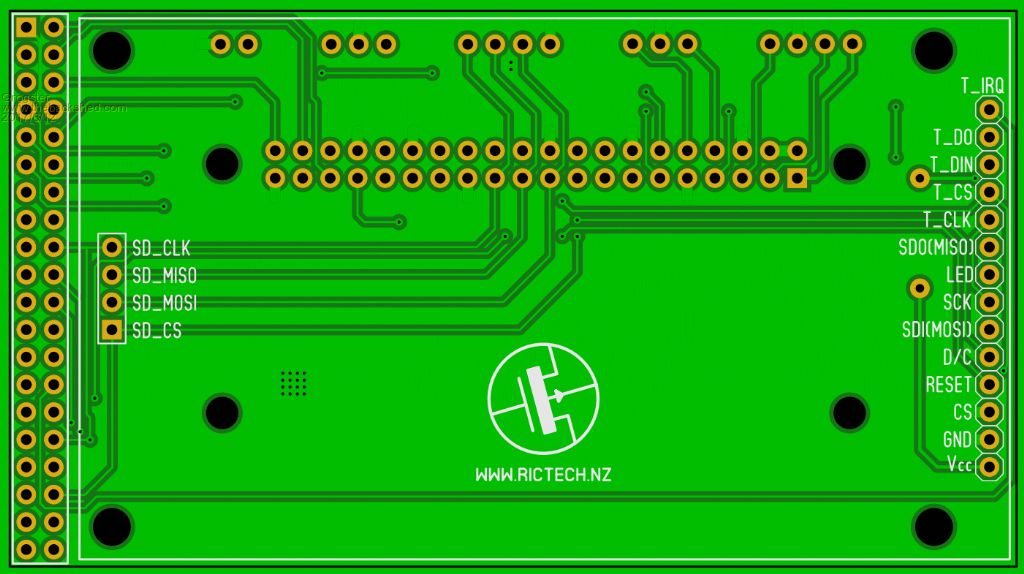 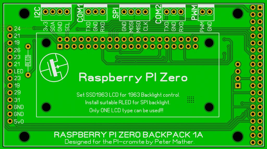 Will that do? EDIT - Forgot to mention: SPI LCD D/C = Pin 29 SPI LCD RST = Pin 31 (same as 1963) TOUCH CS = Pin 26 TOUCH IRQ = Pin 24 SD CS = Pin 33 1963 RD = Pin 36 H/W PWM = Pin 12 All other pins are as already stated. You can use either a 2.8" SPI LCD with touch, or ANY supported SSD1963 LCD with SPI touch and SD card. For the latter, you don't fit the SPI LCD, and instead plug the PI-zero board directly onto the pin-header on the 1963 LCD module of choice. You would need some self-adhesive PCB supports for the arse-end of the PI-zero board, to stop it flapping around on the LCD header, but that is dead-easy to do. Smoke makes things work. When the smoke gets out, it stops! |
||||
bigmik Guru Joined: 20/06/2011 Location: AustraliaPosts: 2979 |
Hi All, Initially I thought "what a great idea" but on consideration there are a myriad of readily available Pi Displays and I see Peter M has a display going already.. Would it not be better to wait until Peter provides some native support for these other displays? I admit I am a NOOBSy here.. but it seems to be an unnecessary addition and makes a 3 stack arrangement. Kind Regards, Mick Mick's uMite Stuff can be found >>> HERE (Kindly hosted by Dontronics) <<< |
||||
| led-bloon Senior Member Joined: 21/12/2014 Location: AustraliaPosts: 209 |
@Grogs very nice .. but does it come in red?  @Mick - all I can say is that the displays are relatively cheap (ILI9341 & SSD1963) and the code is written for them .. sounds pretty good to me. @Matherp - BIG thanks Miss you George |
||||
| bigmik Guru Joined: 20/06/2011 Location: AustraliaPosts: 2979 |
Hi Led-bloon, All, Whilst the ILI9341 are relatively cheap you also have to factor in the price of the adapter board and connectors and components, then the fact is it adds an extra 12mm to 20mm at least to the height due to a 3 level stack.. is it worth doing? I don't want to sway you away from this project, I instead prefer to think that I am offering an opportunity to take a closer look at your design idea before you commit to a production run.. If After all you want to go down that path, great.. I may even buy one. But I think it isn't an ideal outcome, especially due to the added height... you need female/male headers between the Pi and adapter AND between adapter and display, although you could direct solder to the display.. Regards, Mick Mick's uMite Stuff can be found >>> HERE (Kindly hosted by Dontronics) <<< |
||||
| Grogster Admin Group Joined: 31/12/2012 Location: New ZealandPosts: 9910 |
You have exactly the same arrangement on the E100 boards, if you use ANY click module - a three PCB stack consisting of the LCD, the E100, and the Click module. I don't see that as any big deal, frankly. That's just me though. Obviously you Aussies have a hard time with stacking stuff up - we kiwi's are much better at stacking then you guys seem to feel comfortable with....   Also, remember that the LCD's you can get for the PI, take up the whole damn GPIO port header, and it is difficult or impossible to get extra connections on to the unused GPIO pins once you plug one of those LCD displays onto the PI. Hell, the PI-zero is so bloody cheap, there is no reason why you could not permanently mount the PI on the backpack board, so it essentially becomes permanent, dropping you back down to a two-board stack - or 2.5 board stack, if you want to look at it that way... @ led-bloon - default is green, but YES they could be ordered in red! Smoke makes things work. When the smoke gets out, it stops! |
||||
| led-bloon Senior Member Joined: 21/12/2014 Location: AustraliaPosts: 209 |
Just checking the pins in use now .. would like to see any pins not connected going to a row of vias for future connection (possibly at the bottom of the board?) Also, any room for a "click" board adapter area?  Miss you George |
||||
| led-bloon Senior Member Joined: 21/12/2014 Location: AustraliaPosts: 209 |
@Grogs You have directly connected the CS of both LCDs to ground. The SPI LCDs should use an output pin from the pi for CS (not sure if SSD LCD should have a separate CS too) Otherwise it will clash when selecting touch/SD card or anything else on the SPI bus Edit: My bad - NO unconnected pins Miss you George |
||||
| Grogster Admin Group Joined: 31/12/2012 Location: New ZealandPosts: 9910 |
You are correct about the SPI LCD CS - My mistake - will fix. 1963 LCD CS is grounded, as you will always be using that LCD if it is installed at all, but I made a boo-boo with the SPI LCD CS.  I don't think there is room for a Click socket - I will look and see, but the entire bottom edge of the PI module has to be kept clear for connectors on the PI module, so you can't put anything there, which pretty much..... Smoke makes things work. When the smoke gets out, it stops! |
||||
| led-bloon Senior Member Joined: 21/12/2014 Location: AustraliaPosts: 209 |
Grogs The SPI Header at the top of the board is pretty much wasted as it has no CS output. Could I suggest increase header to 5 pins & using COM2 TxD doubling up as offboard SPI CS? At least COM2 RxD could still be used for logging on a serial line say. I would probably mount the Pi Zero between the PCB and the SPI LCD display (albeit upside down) and soldered in, with adequate spacing for connectors. I think too much to ask for a re-design or second version. Using SPI LCD additional (spare) GPIO pins are available at the SSD LCD header .SSD LCD there are no spares available, but COM2/PWM/I2C can be re-deployed. Miss you George |
||||
| Page 1 of 2 |
|||||
| The Back Shed's forum code is written, and hosted, in Australia. | © JAQ Software 2026 |
