
|
|
Forum Index : PCB Manufacturing : vertical resistors
| Author | Message | ||||
| Alastair Senior Member Joined: 03/04/2017 Location: AustraliaPosts: 161 |
I have been using Autotrax for a while now and have successfully had my first boards made in China - happy with the result. It was also my first use of SMD components which took me a while to master but now ok provided I do not try to go too small. 0402 capacitors beat me! My current project is a monitor/control board for the LiFePO4 batteries in my expedition vehicle (Isuzu NPS300) using a MM+ Explore 100. My electronics bg started 50 years ago as a lad, now having retired I have resumed interest and getting up to date. Because of the above I have a lot of through the hole components and will use them where sensible. I would like to make Trax mount the resistors vertical to save board space but cannot find a way to do it. Can the gurus point the way or should I just switch to smd or lay them flat? alastair Cheers, Alastair |
||||
Grogster Admin Group Joined: 31/12/2012 Location: New ZealandPosts: 9982 |
I would have thought that Autotrax would let you mount vertical resistors at 2.5mm pin spacing......  I don't have Autotrax so can't really help, but I was intrigued by your post, as I would have thought that vertical resistors would be allowed for in the package. If not, then I guess they expect all through-hole parts to be laid flat. I remember commercial single-sided PCB's from radios that were all discrete components, and the density on those things was something to behold. All the resistors were vertical, and squeezed in there so tight, along with all the transistors and caps - a real forest of vertical mounted parts.  Those resistors tended to have painted leads, so that when mounted, the paint would prevent the tail ends from touching each other or anything else and causing a short. Memories..... Smoke makes things work. When the smoke gets out, it stops! |
||||
disco4now Guru Joined: 18/12/2014 Location: AustraliaPosts: 1130 |
You can find some vertical resistors in the parts library 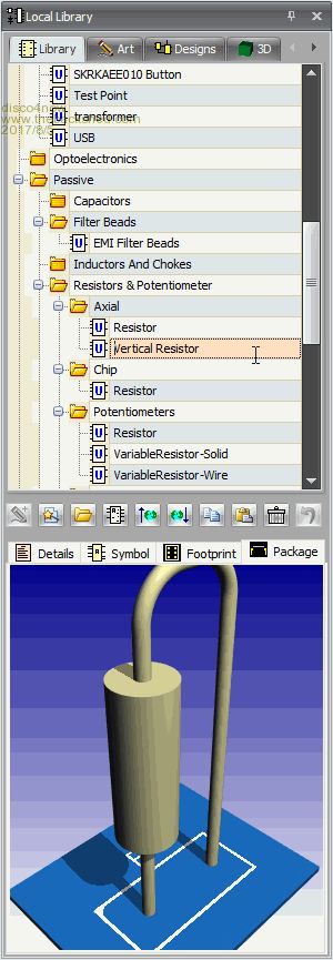 F4 H7FotSF4xGT |
||||
| Alastair Senior Member Joined: 03/04/2017 Location: AustraliaPosts: 161 |
Disco4now - Now why did I not find it there. I searched, tried help - grrr. I knew it would be there somewhere. Thanks. Grogster - yes many times I built or repaired boards like that. I am trying hard to become 'modern' but I have a lot of the old style parts and unless I really need to make things small then I will persist. I have recently moved to the MM domain as I had been using PicAxe for some projects and found the limitation of math functions and FP variables getting too much. I was using it for far more than it was ever intended. I am used to using big systems for scientific stuff. Very impressed by what you guys have achieved in a short time and have found the PIC devices very good especially with the support for screens and touch panels. It makes it easy to have a good user interface. cheers Cheers, Alastair |
||||
| Warpspeed Guru Joined: 09/08/2007 Location: AustraliaPosts: 4406 |
I see no reason why you cannot use a capacitor footprint to mount a resistor, its just two holes and two pads. Cheers, �Tony. |
||||
| Alastair Senior Member Joined: 03/04/2017 Location: AustraliaPosts: 161 |
Tony, yes you are right and that was my fall back but I wanted the schematic to be correct and I was sure it would be there somewhere. cheers Cheers, Alastair |
||||
| Grogster Admin Group Joined: 31/12/2012 Location: New ZealandPosts: 9982 |
Yes, I too was one who migrated to MM from Picaxe, as the MM is just so juicy with it's processing speed, resources and memory. ....with no disrespect to Picaxe.... Smoke makes things work. When the smoke gets out, it stops! |
||||
| Alastair Senior Member Joined: 03/04/2017 Location: AustraliaPosts: 161 |
Success. I managed to squeeze it all in and keep the 3"x2" size I wanted. Learnt more about AutoTrax which is good. Starting to get the feel and how to get it to do what I want. I am sure the experts will see some bad things. Hints welcome. cheers 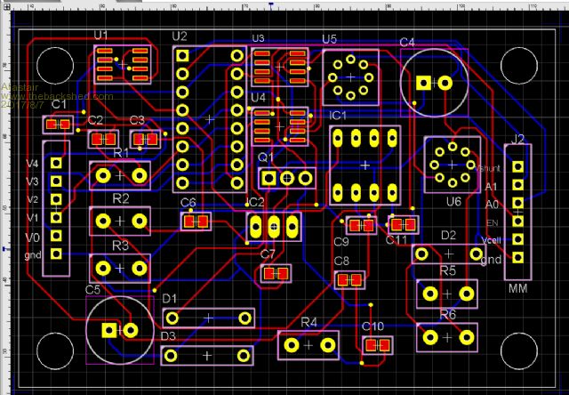 Cheers, Alastair |
||||
| The Back Shed's forum code is written, and hosted, in Australia. | © JAQ Software 2026 |
