Notice. New forum software under development. It's going to miss a few functions and look a bit ugly for a while, but I'm working on it full time now as the old forum was too unstable. Couple days, all good. If you notice any issues, please contact me.
Downwind Guru Joined: 09/09/2009 Location: AustraliaPosts: 2333
Posted: 10:09am 24 Nov 2009
Copy link to clipboard
Print this post
Karl,
I had a thought about something you said with fencing the mill in and using the posts as guide wire anchors.
I am not sure if this will also relate to wires but would think so.
If a support brace is under 30 deg. than it will give no strength as a brace or strut.
So to go from ground level 2 mtr out from centre and a wire up 6mtrs on the tower i would think to be a angle of less than 30 deg.
This might be more inclined to pull the anchors out of the ground than support the tower.
I know you said about putting the posts into the ground on a slight angle but with less then 30 deg wire angle i think they will still be prone to pulling out.
I have read many a story about anchors pulling out and think this has a lot to do with it. ( bad design practice )
I have worked on some drilling rigs that had guy wires and always needed to be more than 30 deg. these would take mass loading to the point we would stretch cables but not pull the deadman (anchor) out.
When done we would hook onto the deadman and rip them out of the ground with a fork lift using a vertical pull easily.
Just something to consider.
Pete.Sometimes it just works
KarlJ Guru Joined: 19/05/2008 Location: AustraliaPosts: 1178
Posted: 12:22pm 24 Nov 2009
Copy link to clipboard
Print this post
Aim is for this thing to be self supporting.
my idea was guy wires are there for some insurance.
Im going shopping Wednesday to a couple of scrap yards.
Price of steel is not what I recall!!!
2nd hand 6" /150mm bore casing is starting to look pretty good -thinking I could weld this to a brake disc drill some holes in the pad area for the bolts into the foundation.
My budget is fast getting blown and I still have to get an inverter at $2K, batteries at $500+ concrete $250
and wish list for christmas Phill Mann dual stator mill...
Luck favours the well prepared
GWatPE Senior Member Joined: 01/09/2006 Location: AustraliaPosts: 2127
Posted: 12:39pm 24 Nov 2009
Copy link to clipboard
Print this post
Hi Karl,
I would think that batteries would cost more than an inverter in an RE system. Sounds like only $500 would be for a few truck batteries. Most decent capacity cells cost this much each, and you would need 6, 12, or possibly 24, depending on system voltage.
Gordon.
become more energy aware
Downwind Guru Joined: 09/09/2009 Location: AustraliaPosts: 2333
Posted: 01:19pm 24 Nov 2009
Copy link to clipboard
Print this post
I do understand how these things blow the budget fast and the surgestions i put forward is not intended to tell you how to build your project or to spend your money. Rather draw your attenion to areas that may be of concern so you can design around them the best you can.
This brings me to another concern, Welding onto a brake disc/drum. Hmmm not sure on this idea, as in my experiance it is not a good idea. You might get away with it if you use stainless electrodes?? but i think the discs are cast iron and you will not weld it without it cracking outside the weld line, as well it will be a nightmare to weld. I would think twice on this idea.
Ring around and see in you can pick up a trashed light pole that a car has hit and salvage the bottom section with the mounting flange on it, or a 6" weld on pipe flange as used in large industrial plumbing like fire systems etc, but i would not use the brake disc.
Sorry to stamp on your idea but think it is flaunt with danger.
Happy shopping and hope you find a few gems.
Pete.Sometimes it just works
KiwiJohn Guru Joined: 01/12/2005 Location: New ZealandPosts: 691
Posted: 09:04pm 24 Nov 2009
Copy link to clipboard
Print this post
A very interesting topic and most informative.
If I may... regarding angles for guys etc. If the problem is keeping the guys inside a small cattle proof area you could use spreaders on the pole in the same principle as a Marconi rig. Edited by KiwiJohn 2009-11-26
KiwiJohn Guru Joined: 01/12/2005 Location: New ZealandPosts: 691
Posted: 09:06pm 24 Nov 2009
Copy link to clipboard
Print this post
Eh? How did that advertisment get in there?
Sorry John, thats a bug, only non-members should get the ads.
GlennEdited by Gizmo 2009-11-26
Downwind Guru Joined: 09/09/2009 Location: AustraliaPosts: 2333
Posted: 02:55am 25 Nov 2009
Copy link to clipboard
Print this post
KiwiJohn,
I dont follow what you mean? How do spreaders give an angle to the wire of greater than 30 deg.
Pete.Sometimes it just works
KarlJ Guru Joined: 19/05/2008 Location: AustraliaPosts: 1178
Posted: 06:55am 25 Nov 2009
Copy link to clipboard
Print this post
I should have started a new thread -for the tower
For guys like us who like to try different stators, rewire jobs, blade tweaks etc the only solution is a tilting tower.
IN my humble opinion much over 8m for this kind of tower is starting to get prohibitive as transporting the sections is difficult.
100x100 x5mm SHS = $35per metre
x4mm SHS = $29 per metre
150x75 x6-8mm Channel section =$31 per metre
I like the channel for the two uprights
call it 6m each side =$372
6m of 5mm SHS for the upright $210.
All the fancy stuff in the foundation for levelling....
great but as Pete says, level it up before starting.
then there is nothing to worry about, no bolts going only half way into the foundation, no flanges, welding etc.
Sorry guys the negatives do not nearly outweigh the positives of this construction. unless...$120 (the 4m of channel buried in the ground) can come up with the welded and bolted soution...and i'm all ears of it does.
Now for all the doubters.....
to 4m high we have:
150x75mm channel (x2) + 3.5m of 100x100x5mm
for the next 2.5m we have 100x100 x5mm box.
for the bump to the tower we have 75mm x6mm pipe x 1.7m.
now for the guys doing the math on the blades......
perhaps could do some math on this
I reckon this will be more than enough.
call it 7m2 blade area for a 3m rotor. for a survive ability of 50m/s or 180km/hr wind. at a total height of 8.2m a read somewhere a 60 odd kg sideways moment at the turbine head
I make it somewhere about (60x9.8x8.2)4800nm at the base
which should be easy for 2x 150x75 x 6mm 100mm apart.
and a 2m deep x 600round foundation full of concrete
at the end of the day a triangular southern cross style windmill tower at 8m is made of matchsticks!!!! admittedly they are about 1.2m apart at the base.
Edited by KarlJ 2009-11-26Luck favours the well prepared
Downwind Guru Joined: 09/09/2009 Location: AustraliaPosts: 2333
Posted: 08:11am 25 Nov 2009
Copy link to clipboard
Print this post
It adds up quickly in cost, dont it.
Did you get a cost on 125x65 C section. I would think it be strong enough for what you need.
The bigest concern will be the weight of the two C sections to get into the hole and stand upright.
I think it would be good to weld some flat plates across the back side of the 2 C sections at intervals to make the 2 as one. Doing this will make it rather heavy to setup but less room for error with the concrete pour.
Im glade you scrapped the brake disc idea as i could see problems with being at the highest stress point.
I think it is good you have kept this all in one thread from start to finish as it is hard to follow a fragmented construction over several threads.
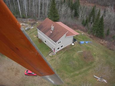
I have been helping a guy in Canada with some electronics and he has a mill ontop of a 42 metre (140')tower, Imagine standing that sucker up????
Heres a photo he sent me.
Pete.Sometimes it just works
Perry Senior Member Joined: 19/11/2009 Location: Posts: 190
Posted: 10:31am 25 Nov 2009
Copy link to clipboard
Print this post
That's a sweet picture!
Perry
KarlJ Guru Joined: 19/05/2008 Location: AustraliaPosts: 1178
Posted: 11:14am 25 Nov 2009
Copy link to clipboard
Print this post
indeed, the mind boggles at what that puppy cost.
if you look really carefully you can see the guy wire anchors on the horizon!!
just kidding
I priced up a big street sign stand 400mm round 12m high.
can have that puppy in the ground for $28,000.....
I didnt price up the 125x 65 C section but if you think that enough I'll go for it on the weight consideration.
I put in a 5.5m 100x100 gal pole 2m in the ground for a shade sail (wall thickness is minimal) and I could barely lift that, I do have a tractor with a crane but its lucky to make 3m high, will do just fine for this.
I always intended to strap the two C sections together but I will bolt one side rather than weld so we can dismantle and lift it more easily.
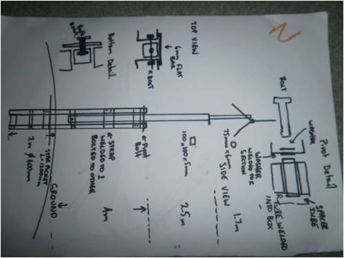
The box section will bolt into the flat bar that joins the two sections at the base of the tilting bit.
here is the sketch for my mate helping with fabrication.
Edited by KarlJ 2009-11-26Luck favours the well prepared
Downwind Guru Joined: 09/09/2009 Location: AustraliaPosts: 2333
Posted: 12:27pm 25 Nov 2009
Copy link to clipboard
Print this post
Looks like it should work fine.
Had to turn my screen on the side to view it. (just kidding)
May as weld some lugs on for guy wires just in case you find you need them later. Easier now than later.
The way i see it is there is two ways at building something like this.
1) Big solid steel and spend a mere fortune.
2) Use lighter material and engineer it to be strong.
I would choose option 2 and would think 125x65 would work for both options. To be safe i would weld on some plates (tags) with a 1/2" hole in them onto the C section around 3 mtrs up so 4 braces could be bolted on later if needed, going out to a footing on each corner. You could use something like 40mm pipe as braces if they are needed. (they would give a push/pull support)
A little plan B planning now will give greater options later.
If the support braces were adopted then i would think you could drop down to 100x50 and also perhaps even less depth inground for the main tower beam as you would be creating a 5 legged tower with a lot of lateral support. ( think of a water windmill)
Lighter materials and good design i think can be stronger and more cost effective than just brut steel size.
So far i have tried to offer thoughts to your designs and not tell you how to build it, but the cost you have listed above i think is scary and feel you could engineer it cheaper and stronger with better use of materials with a few thought outside the square.( or is it more to a square )
If you viewed this as designing with the ability for it to be semi free standing and then concreted it in for stability i think you would cut a lot of cost and weight from it. ( steel is basically sold by weight )
Whats your thoughts.
Pete.
Sometimes it just works
Downwind Guru Joined: 09/09/2009 Location: AustraliaPosts: 2333
Posted: 12:53pm 25 Nov 2009
Copy link to clipboard
Print this post
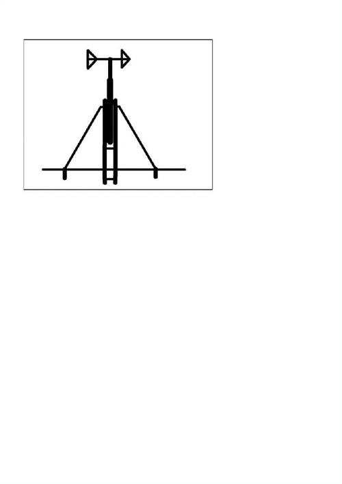
Something like this.
Pete.Sometimes it just works
Tinker Guru Joined: 07/11/2007 Location: AustraliaPosts: 1904
Posted: 02:18pm 25 Nov 2009
Copy link to clipboard
Print this post
You can see that principle used on yacht masts & sometimes on electricity power poles.
The idea is the guy wire goes at 30 or more degrees from the mast attachment to the spreader tip and then nearly vertical to the ground. The angle of the guy wire above and below the spreader tip should be equal, hence the spreaders are angled upwards.
Wind pressure put the mast & spreader under compression load and the guy under tension.
Thinner mast sections can be used since the bending moment is now reduced, there still needs to be a *lot* of weight anchoring the guy wire rope.
For a windmill, at least 3 spreaders at 120 degrees from each other will be required.
This idea is useful for a limited area to locate the mast on.
Klaus
Downwind Guru Joined: 09/09/2009 Location: AustraliaPosts: 2333
Posted: 02:43pm 25 Nov 2009
Copy link to clipboard
Print this post
Ok i understand now. Basically struting it back onto the tower.
As you said need big heavy anchors.
With a 30 deg or greater angle the anchors can be much smaller and give good strength and not so prone to pulling out.
Its just a matter of space verses anchor size.
Pete. Sometimes it just works
KarlJ Guru Joined: 19/05/2008 Location: AustraliaPosts: 1178
Posted: 10:23pm 25 Nov 2009
Copy link to clipboard
Print this post
This is my shopping list
I decided to go up to 125box section to match the sides
125 in 4mm wall is stronger than 100 in 5mm wall.
125x 65 C section 2 of x 6M (looks like I beam but only half)
125 x 125 box section 4mm wall x 6m + 1x1m (add on the outside to add ballast if required)
Round bar 25mm id 3.2mm wall (1” bolt through pivot does up on this) x 130mm long
Round bar 32mm id 4mm wall ( 25mm bar turns inside this to allow pivot) x125mm long
Flat bar 50mm x 5mm thick x 250 long x8 pieces (use to hold the two sides together)
Flat bar 100mm x5mm x 117 long x 5 (will cut these up to make round pipe fit into square pipe)
65mm NB 6mm thick round tube x 2m long.
Pivot
1” bolt with suitable nylock nut and spring washer and 4 flat normal washers length 150mm shank.
Bolts to secure tower in upright position
2 x ľ” bolts with nylock nuts and 10 flat washers 20mm shank length.
9 pieces of chain for guy wire anchors if it ends up not strong enough.
Edited by KarlJ 2009-11-27Luck favours the well prepared