
|
|
Forum Index : Windmills : TESTING BLADE STRENGTHS & FORCES
| Author | Message | ||||
fillm Guru Joined: 10/02/2007 Location: AustraliaPosts: 730 |
Continued from "Aluminium Blades Up & New Hub" To give myself and others a guide I load tested both types of blade materials which are used in making this airfoil using the common mount method of rivets and bolts , the small pieces were attached to a 25.4mm piece of s/s tube and set up in my press , I fitted a lower pressure gauge to allow for a more accurate pressure reading at lower pressures . First test 2 x 3/16 rivets in PVC blade piece 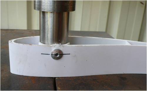
Set up in press with marker line to see first movement. Rivets started cutting through at approx 150kg - 200kg ( Temp was 30 deg C ) 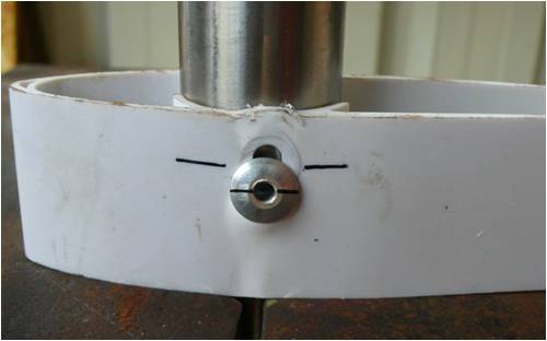
at 250kg the rivet let go from what appeared to be a build up of material under the head and poped it off. 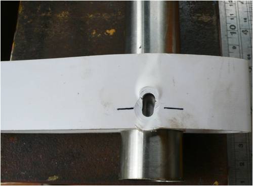
Test2 Aluminium 3/16" rivets with aluminium blade piece , I took it to 500kg then 600kg at that point it sheered 
Test 3 Changed to rivets I normaly use ( I think they are s/s as they are not magnetic ) 3/16" . Al rivet frm test 2 shown 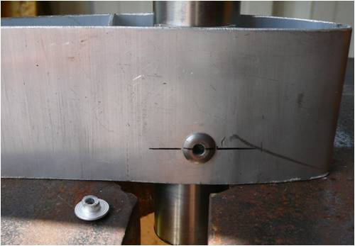
Test 3 - 750 kg no movement , 900kg sheered after about 1mm of movement . 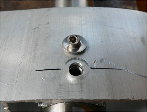
Test 4 - 1/4" bolt low tensile 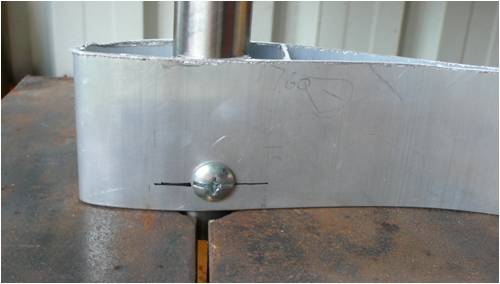
500 kg no movement , 1000kg ( 1Ton ) no movement , 1250Kg moveing and cuting aluminium , kept going at 1250kg then bolt sheared 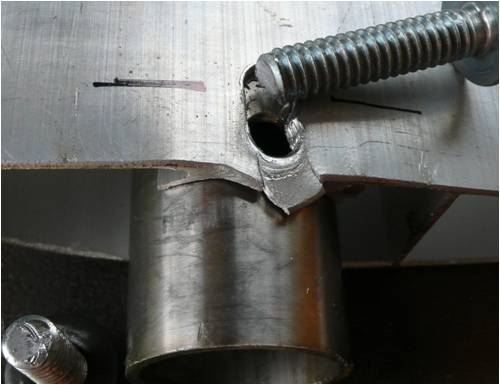
As I have already seen movement in the pvc 3.150 set with 6 rivets of about 1-2mm after reaching 750rpm I would ascertain that at that speed the centrifugal force on the pvc blade was 450kg to 600kg to allow the rivets to start cutting through the blade , as I have not added extra rivets and there is now a build up in front of the rivet I would say that it will take 750kg + and higher rpms to get further movement or softing of the blade material due to the heat of summer . With this info I decided to use 4 rivets and the one bolt which combined should give a total load carring ability of 2500kg which is 4 times the maxium force that I have caculated to have been exerted of a blade of similar weight . The one point I will make is that the outer rivets will be loaded differently untill all of the load surfaces have made full contact to share the load evenly , having correct sized holes with and snug fitting rivets in both tube and blade is important . Gyroscopic and yawing forces. Below is a pic of how close I run my blades to the pole 150mm on tower 2 and 200mm on tower 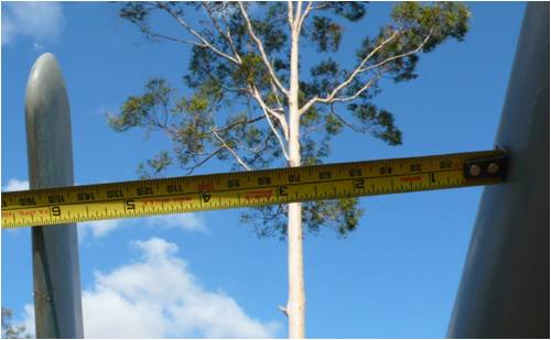
The blades shown below are my old ABS blades which have been through quite a bit , origionaly they were 3.2 m but after hitting the deck at 780rpm and being a bit damaged I cut the root section of to make 2.8m . At 3.2 m they were very flexable and still are at 2.8 , not once ever have thy looked like they were going to hit the tower . As you can see from the 2 pics below the first with a 5kg weight at the blade tip and the second with 10 kg approx 1/ 3 in from the blade tip if gyroscopic force or yawing force at the end of the blade reached this force , they would be history .At high speed in high wind I have watched these flexing but the tips don't get any where near the tower , so how much of these forces which get labled as massive and extreme are really there when blades are in full flight , obviously not this much , or does centrifugal force come into counterbalance the other. 5kg at tip 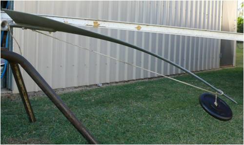
10Kg approx 1/3 in from tip 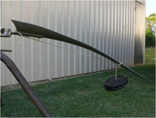
The two pics below are of the 1.5m Aluminium blade , I decided to see how much these are good for in a beam strength deflection type of test . 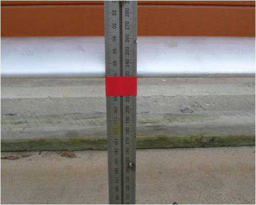
About 20mm deflection with 78kg in the middle area of 200mm either side of centre and supported 50mm in from each end and no internal tube 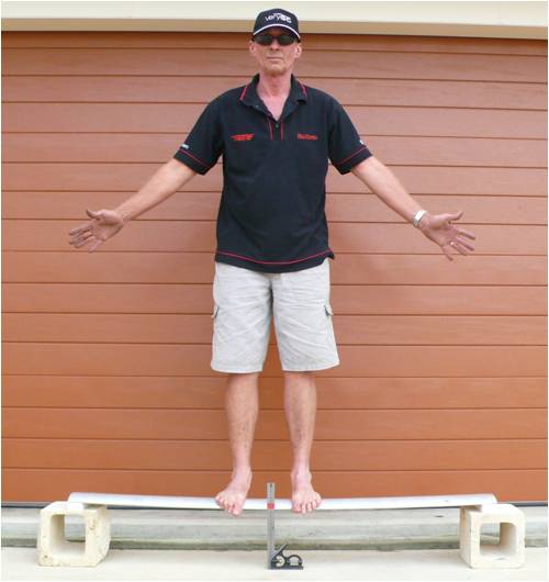
There was no permanant bend left in the blade . With all the infomation I have through testing and observation has left a few questions in my mind with regards to how much support these blades require , as you can see from the test of me standing in the middle section and from the sheer tests Anyway I still decided that the safest option was to go with the 25% solid /75% tube & Min 6 x 3/16 rivets ( not aluminium ) + 1 x 1/4" bolt as the standard guide line for now which is pretty well the same as the PVC mounting . This set has ended up under this guide line , I have decided to go with as a trial and the lengths and weights are listed below for those who might want to do the maths on forces . Overall Dia- 3.2mt - Hub mount Dia 250mm - Blade length 1450mm - weight 1750g + 2 x 11g end caps S/S tube - 950mm x 25.4mm X 1.5mm ( 920mm from outer clamp face ) Overall weight 836g 4140 solid - 300mm x 22.3 ( 260mm from outer clamp face ) Overall weight 980g 1/4" bolt - 200mm from outer clamp face 3/16" rivet- 500mm 800mm front 550mm 850mm rear This gives me a ratio of 5.5 : 1 at the load point of the solid to tube . Furling starts at 35klm and fully furled at 45klm to 50klm Anyway I hope this gives all here some food for thought although of course I expecting some flack from some . PhillM ...Oz Wind Engineering..Wind Turbine Kits 500W - 5000W ~ F&P Dual Kits ~ GOE222Blades- Voltage Control Parts ------- Tower kits |
||||
| Perry Senior Member Joined: 19/11/2009 Location: Posts: 190 |
Phil, Nice post and it looks like you have done quite a bit of work with your testing. It's also good to see that there is some form of structural component as in our last discussions we were assuming they had none. Looks like the rivets will protect from pullout as was assumed all along because you can always add more rivets but the concern is with fatigue cracking around the rivet holes. Anyway, you've heard that more times than these blades will see in fatigue cycles so I will leave that to others to discuss :) Do you have any blades performance data? Power curves, efficiencies, TSR, that kinda stuff? Keep us posted, Perry |
||||
| Gizmo Admin Group Joined: 05/06/2004 Location: AustraliaPosts: 5187 |
Hey Phill Top notch post mate, well done. Perry, the blades use a GOE222 profile. This profile has been used by the Windcharger turbines for many decades, a proven performer. There is a timber version made by Royal Fabrication in the USA, and they have done some serious testing on power and efficiency. http://www.royalfabrication.com/performance.htm I can say, as far as I know, anyone who has tried the blades has been impressed by their performance. The blades dont have any twist or taper, but make up for it with a profile that generates good brute power, and they are quiet running to boot. Glenn The best time to plant a tree was twenty years ago, the second best time is right now. JAQ |
||||
KarlJ Guru Joined: 19/05/2008 Location: AustraliaPosts: 1178 |
excellent post Phill, well done. As far as blade strength is concerned, I think the profile has lots to do with it and the shear web inside makes it like a little I beam. even if there are some fatigue issues with either material (stainless and aluminium) they should last long enough that they pay their way which is a lot more than most blades in the market could hope to do. EG windgrabbers and things like that which would be far more susceptable to the fatigue talked about in the other posts. Lastly , fatigue is related to bending and if the bending is minimal as you have shown, then the fatigue issues should also take a very long time to surface. BTW: there are plenty of red faces in engineering land when it comes to designing things bet very few red faces when it comes to tested products. EG -mechanic say no way that will last, engineer says it will be fine but breaks mechanic beefs up over and above what he thinks it will ever see and 100 years later I dig it up and although technology surpassed it, it still works. (then I sell it for SCRAP) Luck favours the well prepared |
||||
| dsmith1427 Newbie Joined: 21/07/2009 Location: United StatesPosts: 5 |
Very thorough and a job well done! Thanks for sharing it with us. Fatigue is a function of cyclic loading (bending, tension, shear, torsion) and can occur when maximum stresses are less then ultimate stresses and may be below the yield stresses. When you perform preventative maintenance you may want to look for signs of fatigue which may include cracking, hole elongation, etc. My knowledge of fatigue is limited. Hopefully other people on the forum can add more insight. Happy Holidays! Don |
||||
| JimBo911 Senior Member Joined: 26/03/2009 Location: United StatesPosts: 262 |
Phill Dam good job! Fantastic mounting system. Balancing well defined. I would think that the Alu blades are as strong or tougher then the PVC. Looks like I won't be the only member that will be using a bolt or bolts to mount these type of blades. I do believe a ridge mounting system has a lot to do with survivability and longevity. Jim |
||||
| KarlJ Guru Joined: 19/05/2008 Location: AustraliaPosts: 1178 |
SOLD! inspirational for this forum really, someone that does more than they talk ....like me of course  Luck favours the well prepared |
||||
| neil0mac Senior Member Joined: 26/12/2009 Location: AustraliaPosts: 210 |
Could it be that the plastic blades started to fail because the pop rivets were not in full contact with the material? I.e there is a small gap under the head around the shaft of the rivet which allows for compressive forces to spread the plastic perpendicularly to the shaft. Perhaps using an aluminium plate over the blades (or a smidgin of gap filling epoxy resin that could have the excess cleaned off easily) would eliminate this? Small details perhaps, but any movement around the rivets could turn static loading into (minimal) impact loading when in operation. |
||||
| KarlJ Guru Joined: 19/05/2008 Location: AustraliaPosts: 1178 |
FYI Phill pic 3x the diameter of the rivet or bolt is the aviation industry standard minimum distance to the edge, which is why you have some tearing of the material there 4x the diameter in composite material (like PVC) not knocking the test, still clearly shows the intent but for the mill, give them 3D from the edge min. Luck favours the well prepared |
||||
| The Back Shed's forum code is written, and hosted, in Australia. | © JAQ Software 2026 |
