Notice. New forum software under development. It's going to miss a few functions and look a bit ugly for a while, but I'm working on it full time now as the old forum was too unstable. Couple days, all good. If you notice any issues, please contact me.
Just spent a while reading the Series Cap threads, and thought I'd jot down some ideas.
Hopefully the image appears ok.
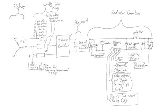
Major sections are:
F&P Stator, producing 3ph AC
Switchable Series Capacitors on each lead from stator, with a shorting relay as well.
3phase rectifier the convert to DC
Very large Electrolytic caps just after rectifier to act as flywheel - potential energy store
zener diode to drop high voltage from genny and cap bank(could be in the hundreds of volts)
Small PicAXE chip to perform a few tasks:
Measure Cap Bank voltage(Vsense0), and
alter series caps(A-F) to obtain highest voltage for available RPM(from AC coupled Opto-coupler).
Can also bypass Caps(S) for testing/discharge
Measure Output Voltage(Vsense1) to determine load on system, and adjust PWM between 0 and 100% to suit.
Inductor, Schottky(s), and MosFET(s) form standard Buck Switchmode.
If PWM is 33%, consider it a 3:1 gearbox - 100V 5A from turbine becomes 33V 15A(ignoring losses) for charging 24V batteries. Cap Bank(Flywheel) continues to charge(speed up) while PWM is in off state.
In theory it might combine the ideas of the series cap, and buck PWM converters into one solution.
Load matching from Stator to Rectifier, then from Cap Bank voltage to required output voltage... I wonder.
Any ideas?Nigel Weeks
nweeks at karbonit dot com
Greenbelt Guru Joined: 11/01/2009 Location: United StatesPosts: 566
Posted: 06:35am 30 Dec 2009
Copy link to clipboard
Print this post
NWEEKS;
quote; (Switchable Series Capacitors on each lead from stator, with a shorting relay as well.
3phase rectifier the convert to DC ) EQ.
As I prepare to post , This Person half a world away has
Logged on and destroyed my humble offering.
So with hackles raised I will post it anyway since I have
worked on it, bits and pieces over the course of a week
with a reluctance to show my Ignorance to people who Know
or think they know different.
Nigel; I will not pick your circuit apart for errors since I would not recognize a dozen if they were linked together. I'm just a hair bit better with Discrete
devices. Old Valves and such.
I'm very much in agreement that your ideas have merit
for at least a good test with careful attention to capacitor values and coil inductance and weather Parallel or series cap's give the best performance.
at stator output. Some of this has been noted in the forum sometime back but covered quickly.
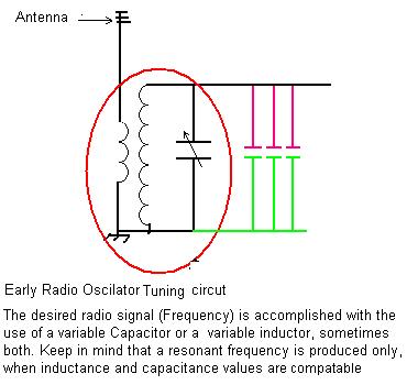
In radio a resonate circuit will pass the maximum current when the frequency of the signal remains constant. If the Frequency changes, then the circuit is un balanced and the inductive reactance is out of phase with capacitive reactance. The values must change to make the new frequency resonant. (Flywheel).
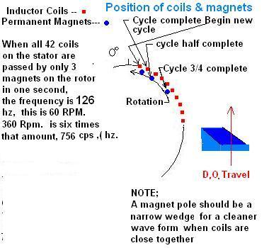
When The Coil of a alternator moves past a Magnet and moves on, an electrical cycle has been created, ( Dubbed Hertz (hz .) a few decades ago.
When using the number of coils found on the F&P washer Motor and many magnets, This alternator is capable of exceeding the household frequency at less than 60 rpm (1 rev. per second).
At 360 RPM, Well, Count your magnets and coils.
How about 650 rpm.
Now back to the Capacitors with variable wind speed and different coil windings?? Now a tiny radio receiver compared to a thousand watt generator sounds ridicules , But Here! How do you get 30,000 watts on a transmitter antenna to pulse at 1.7 megahertz.
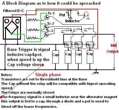
In the case of wind turbines with Capacitors on the output it would seem that a means of switching a series, not series but parallel, of caps. adding and removing a cap when the wind changes would assure a closer match to a resonant circuit at all speeds. Perhaps a picaxe or similar chip with three or more outputs could switch a power relay for this purpose.
Note, this post is meant to convey a thought and minimal effort to the math I,m certain errors exist but the Mill
needs a tuneup. I am hopeful this will bring out the radio engineers.
Time has proven that I am blind to the Obvious, some of the above may be True?
KarlJ Guru Joined: 19/05/2008 Location: AustraliaPosts: 1178
Posted: 06:46am 30 Dec 2009
Copy link to clipboard
Print this post
looks complicated, keep reading, you'll eventually get to the voltage doubler from Gordon.
even simpletons like me can understand That it works.....
but not necessarily why it works.
24V is an easy re-wire and gets good results, I think the only reason for this would be to reduce transmission losses, but you dont want to transmit High frequency AC either so circuit ends up split all over the place and you end up with wires running everywhere.
Big caps that handle 200V 1 farad are tough to find and probably hideously expensive to boot
KISS is the go, copper wire out to the mill =big at least the kids can dig it up in 30years and it will be worth more than my house is now.
I went for 200m of 16mm2 single which is 35KG of copper! for $240....Stuff all loss at 48V even with 100m run and 20A in the cable (which will happen unbelievably rarely if im lucky)
KarlLuck favours the well prepared
Greenbelt Guru Joined: 11/01/2009 Location: United StatesPosts: 566
Posted: 09:20pm 30 Dec 2009
Copy link to clipboard
Print this post
Page 7 and 8 in this forum covers the gist of the Idea.
Costly cap's appear to be the end of tests Though Gordon,
OZ, and others found an avenue of progress that resulted
in efficiency not known before. Kudos to their perseverance.
A Question to OZ if you will? A chip using frequency as an input and a voltage value output connected to a diode and used EDIT; to charge a standard Cap.to its rated voltage when the frequency is high, This DC charge Would limit the AC component value of the Cap, then when the frequency drops the voltage drops and the cap can begin to add capacitance.Very automatically END EDIT; If so, This could be used to trim or alter the value of the larger Cap when installed parallel. What are Your thoughts?
Edited by Greenbelt 2010-01-01Time has proven that I am blind to the Obvious, some of the above may be True?
oztules Guru Joined: 26/07/2007 Location: AustraliaPosts: 1686
Posted: 12:15am 31 Dec 2009
Copy link to clipboard
Print this post
Greenbelt...
If you read the caps thread in full... you will be very old.... but you may find that adding caps is far more complex than first blush.
The caps can change the PF of the alternator, change the effective MMF of the magnets acting on the coils, change the inductive reactance of the circuit with frequency and change the synchronous impedance of the system and armature reactance in particular.
They can push back the current limit curve, they can alleviate stall problems, and be used to boost voltage... or all of the above concurrently.
All thats not bad for two plates separated by a gap.
Gordon was able to mix and match caps and loads to get I think 1kw out of a 100 stator .... single.
This is without relays, without pwm, and without complex algorithms..... and the caps are dirt cheap if you look around for them. (when they are on special at Rockby's... cents each...)
So my recommendation is .... don't do it. Keep it simple. Use caps only, or at the most a boost converter like Bob's recently posted one, but never dynamic switching with relays.... I would add buck converting here too, but the F&P is current limited, so there is a finite current to design for..... otherwise no buck converters unless your a power engineer or have shares in fet companies..... it will end in tears. The relays will be clattering all the time... and if you add hysteresis, you will be so far behind the game as to be useless.
Rant aside, you already know the answer to your question. Being an old Valve buff (from your opening comments), think of your plate circuit. You have 400vdc on the plate "biasing" the coupling capacitor.... did it interfere with your audio signal, or change the cap value?
I don't wish to ruin your fun, and it is cool to dream up all sorts of high tech solutions to problems that have been solved simply before.... but the caps seem to solve the dynamic dilemmas better than our algorithms so far.
With Gordons axfx, the load matching is crazy bad . Without capacitors it would be unusable. But he has cube law buck and boost control with no electronics, and no magic smoke.... and has managed to match the load very well for miserable cost.... good outcome.
Have fun with it though.
.............oztules
edit: I was avoiding this thread like the plague, as I knew I would only rain on others parades or be seen as being negative, but you asked by name.... so....
Edit#2 on your edit:
[quote]EDIT; to charge a standard Cap.to its rated voltage when the frequency is high, This DC charge Would limit the AC component value of the Cap, then when the frequency drops the voltage drops and the cap can begin to add capacitance.Very automatically END EDIT [/quote]
Hmmm, I can see what your up to I think, but no. I suspect that this probably going to be improperly put, but maybe the general thrust may help us a bit.
The DC bias you wish to impose on the cap is fine (think plate circuit) I suspect that the AC simply modulates this DC component so that the AC signature is still there..... just as a coupling capacitor does. We may only be amplifying millivolts, but the cap will be DC biased with 400v.... the information is still there and it's effect is still passed through the circuit.
or put another way....
Remember, no electrons actually jump the gap/dielectric..... so no current actually flows across the gap. The DC component simply makes one plate electron deficient, and one plate electron rich. Any incoming signal will simply add or subtract from that stockpile .... basically .... and forces current flow proportionally in the rest of the circuit.
Remember, charging up to the rated voltage.... just means we haven't penetrated the dielectric.
And yes I'm open to better analogy or corrections.Edited by oztules 2010-01-01Village idiot...or... just another hack out of his depth
Greenbelt Guru Joined: 11/01/2009 Location: United StatesPosts: 566
Posted: 08:13am 31 Dec 2009
Copy link to clipboard
Print this post
Thanks OZ;
I live in seattle we're Used to being Rained on.!
I respect your opinion that's why I ask
Time has proven that I am blind to the Obvious, some of the above may be True?
KarlJ Guru Joined: 19/05/2008 Location: AustraliaPosts: 1178
Posted: 09:24am 31 Dec 2009
Copy link to clipboard
Print this post
i think guys like OZtules have forgotten more about this stuff than most of us will ever know....
I feel privileged to receive his wealth of knowledge, one day I get down to those roaring forties and do some paddock bashing in his ev!
Happy new yearLuck favours the well prepared
GWatPE Senior Member Joined: 01/09/2006 Location: AustraliaPosts: 2127
Posted: 11:51pm 01 Jan 2010
Copy link to clipboard
Print this post
Hi Nigel & Greenbelt
Oztules has pretty well summed things up while I was on holidays.
I measured approx 1kW peak from a F&P single stator mill. This was into a complicated loading of batteries and GTI.
The AxFx mill has pushed the flexibility of cap arrangements to provide effective boost and buck load matching. The parallel aspect of these systems means NO relay or electronic switching. If you get to make a relay switching system for a windmill you will appreciate how important it is to remove the relays. The click clacking would soon cease with the windmill electrically loaded unfavourably.
The aspect of resonance ????
I am not an electical engineer, but I have found that my cap arrangements work better away from component resonant frequencies.
I noticed problems with loading of my F&P mill when the caps were operated close to resonance frequencies.
Gordon.
become more energy aware
Greenbelt Guru Joined: 11/01/2009 Location: United StatesPosts: 566
Posted: 01:27am 02 Jan 2010
Copy link to clipboard
Print this post
Gordon;
Interesting ,
I'm certainly not an engineer, my claim to no fame is an
old old book that taught many people how to build a radio Receiver and a transmitter that would allow conversing with people in OZ, from the US.--- When the ionosphere was willing.( HAM RADIO)(Book) ELEMENTS OF RADIO By Marcus and Marcus Published by Prentice Hall. I have picked up some knowledge from its pages.
NO I did not build the Radio but the book has been with me many years.I may not look at it in 10 years but its a good reference.
(Back to topic.
About resonance. I have wondered why you steered away from it? After reading your post about loading problems
at resonance, I recall something I read in this Book. In effect, it says a resonant circuit contains infinite current and voltage is Zero??? this was in the very first
chapter, (tuning circuit). Without voltage to the load there would certanly be a problem.
Thanks for the follow up to OZTULES reply. Happy N-Y.
We're A Day Late Ya know. BTW if you want to see the water go down the hole the way we see it you must look at the sink drain from the other end. try this in a glass of water.Time has proven that I am blind to the Obvious, some of the above may be True?
GWatPE Senior Member Joined: 01/09/2006 Location: AustraliaPosts: 2127
Posted: 02:29am 02 Jan 2010
Copy link to clipboard
Print this post
Hi Greenbelt,
This would be a node, probably be in relation to a filter design.
I saw this in parallel resonance, with the cap becomming effectively a short cct. Cap heating seemed to be the biggest problem, and we need to keep the caps cool for long operating life.
The direction the water goes down the drain has a lot to do with the shape of the bowl as well.
Gordon.
become more energy aware
Greenbelt Guru Joined: 11/01/2009 Location: United StatesPosts: 566
Posted: 03:32am 02 Jan 2010
Copy link to clipboard
Print this post
GWatPE;
Yes, A tuning circuit would be a filter passing only the
desired freq.
The only way to achieve resonance in a mill would
be to have instant control of capacitance up and down
and continuous. I can see this would require a house full
of circuits. a current Transformer to add resistance so the voltage can be boosted to a usable level. Thanks to OZ for the Rain I'll sit here and watch it go down the drain. PS My drain is shaped like an OZ drain. I like to be different. Time has proven that I am blind to the Obvious, some of the above may be True?