Notice. New forum software under development. It's going to miss a few functions and look a bit ugly for a while, but I'm working on it full time now as the old forum was too unstable. Couple days, all good. If you notice any issues, please contact me.
Bernhard Newbie Joined: 01/02/2010 Location: CanadaPosts: 12
Posted: 06:18pm 02 Feb 2010
Copy link to clipboard
Print this post
First @ "Sonny"
Unfortunately one needs to use a credit card to deal with e-bay? I am not sure about that, but I HATE credit cards and if I had one I'd be too chicken to use it for internet transactions.
The problem with the Canadian duty would also still rear
it's ugly head. I bought a foundry set from Pyramid engineering in California once and had it shipped by U.P.S. That was a NIGHTMARE!....but in the end the foundry was worth it. I was able to cast my own brass bar stock for my lathe and all kinds of stuff...
but the "Import" red tape was a nightmare!
Can I "con" you to come to Canada for a fishing/hunting
vacation and bring me some of your mag's ?
@ AMUN-RA
Yes I did see that myth buster episode.
On the other hand Chemical engineering was my life long profession. And what I prefer to call "spectacular chemical reactions" was the love of my life.
My nickname with my ex colleagues is "Dr.Destructo"
...and when I served with the military engineers they
put me and my twisted sense of humor to full use!
I was just clowning around with that "hiding under my workbench" remark and the noises like in the "Das Boot" movie.
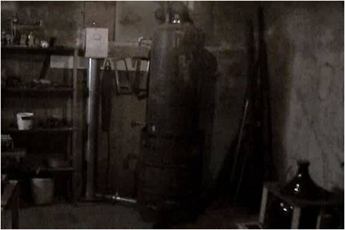
When I pressure test a vessel I do it of course by the conventional method
.....pressurizing with cold H20 and not with steam or compressed air!
all that happens, should the vessel fail is, it springs a leak. At the same time you can detect even the slightest leak because without a "gas cushion" the pressure drop shows up within seconds.
I did know that a hot water tank does not get CSA approval (here) unless it is engineered to at least twice the normal operating pressure.
....else I wold not have gone through all the trouble welding together a barrel wood stove with that tank being in effect the lower chimney section.
Like I said my cam takes lousy pictures indoors.
..and now I am really embarrassed!
I noticed on the right of the picture you guys can see that I make all kinds of other"home-brew-power"..
....or "power-home brew"
I forgot to wheel my ferment jug out of the way...
Would you believe the "it's strictly for medicinal purposes" line?
But I do thank you for your concern.
What I do need are a lot more magnets, than what I can salvage from hard drives...
Some times I get lucky. The local school generally gives me all their junked PCs.
Maybe I just wait for their next "upgrade".
.....then I get a windfall, usually 30-40 PC's.
Edited by Bernhard 2010-02-04
Bernhard Newbie Joined: 01/02/2010 Location: CanadaPosts: 12
Posted: 08:21pm 02 Feb 2010
Copy link to clipboard
Print this post
I hope you don't mind if I quote you again.
I wish to address why I "twisted" my prop and how I got the idea for the construction method.
I can't take credit for either.
WW1 props were made exactly the way I make mine!
Then the "twist" and the fact, that as you also must have noticed blade width which remains the same from root to tip.
....not like everybody else does it using a narrower width near the tip...where you get your best power yield.
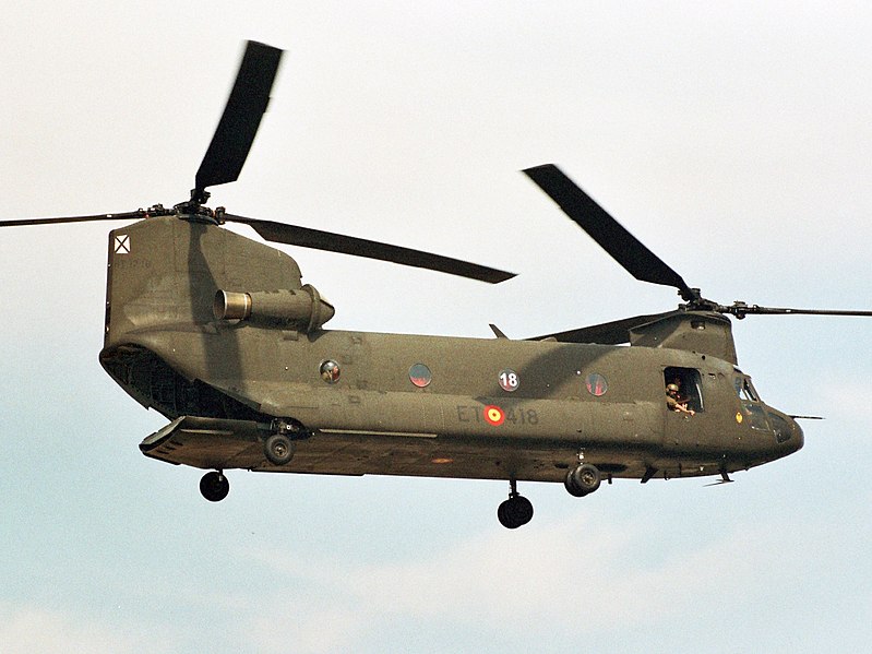
I had a lot of opportunities in my professional life to closely study "Herc" props, especially when that happened:
I had no trouble to stand there all day and feel the torque of the prop every time there was a little bit of wind that day.
I was impressed!....as you are also able to observe the
prop blade width is not tapered over the entire length of the blade....also they use 4 blades not 3 like everybody seems to fancy for windmills.
So, again I can`t claim credit for what I simply copied from a Hercules Transport.
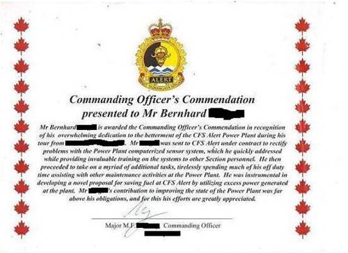
You may be curious what the hell happened there.
Both at Thule air force base and the "listening post" CFS Alert on Ellesmere Island (400 miles south of the North Pole) we use nothing but Jet fuel even for the CAT Diesel powered Power Plants to make our hydro.
Fuel is flown in at the rate of 14 gallons consumed by transport to 1 gallon delivered.
It was my job to improve this sorry situation.
Which I did manage to do and for which I did get credit:
Sorry I had to censor out my last Name, the C.O.`s and the date!
So what happened here: they started de-fuelling the starboard tank and the air crew went inside for coffee.
The pumping was a bit faster than they thought and they missed the time slot when they should have switched to the port side tanks.
Well it being the military no-one got fired!
But I think the load master did need a change of underwear!
Back to the "twist" as you call it.
With the WW1 laminate propellor construction method, cutting strips on a table saw, then "fannig" these like a deck of cards you can of course select any kind of "twist" you desire.
You can make it 65 degrees pitch change from root to tip or as little as 20 degrees or whatever...
I am impressed with the guy here, forgot his name right now, that uses the 2 offset guide rails/Alaska chainsaw mill method to make his prop...!!!!
But he is limited by the thickness of his stock lumber
as to how much pitch/distance variation he can "milk"
from a particular piece of lumber.
Also if you have a "knot" in the lumber, that will be a serious weak spot.
When I hit a knot when I rip my laminate slices I simply turn that "knot" section around so it overlaps and gets sandwiched with a flawless portion of the next strips.
Once the "fanned" stack is glued it is just a matter of minutes to sand the steps with an angle grinder and a decent "floppy" grinding disk.
Material waste is minimal....once you have set the rip fence on your table saw.
I just thought you guys might find it worthwhile to revisit World War 1 propellers and what does work so well for a "Herc"....and has worked very well on my
test rig....start-up cogging?....I don`t even worry about it!
Edit: I just wanted to also briefly discuss this PVC pipe method to make a prop:
This method forces such a taper cut and the selection of the proper OD size pipe.
And again at the tips where you would get your best torque yield the blade then presents a minimal surface to
the relative incoming air flow.
With a spruce laminate you need not fear the resulting
force at the tip, which is vectored into the direction of
rotation anyway as the prop gathers speed!
With PVC not being the strongest Material that may be a good thing, that the tips yield less force....but where I live extension cords break in winter temperatures like a dry twig...and so does a PVC prop!..even if you taper it.
Edited by Bernhard 2010-02-04
Downwind Guru Joined: 09/09/2009 Location: AustraliaPosts: 2333
Posted: 02:13am 03 Feb 2010
Copy link to clipboard
Print this post
Still interesting.
There has been much posted on many sites about blade design and i am far from a expert on this.
I would think your blades would be low speed due to the drag out near the tip that you quote where the power is.
Yes there is power in the tip as well as drag.
This design might be good if motor driven as you would want to get as much bite on the air as possiable.
There is mass information on windmill blade design around and as much research as well, and from my reading it is advised against the large tip area.
I understand you have a very good back ground and great knowledge but think you might be missing something in blade design when it comes to wind energy.
This dont mean your blades wont work as they have proven to work, but there will be negatives to them in windmill applications.
To start with they may be near imposable to stop in strong winds and burn your windings up.
The simple fact that you required gearing implys that they are low speed and you have induced losses with the gearing to start with.
A different design and the need for gearing would not be required.
Your blades are designed for torque rather than speed.
Its a fine line to get both in balance to suit a windmill.
Your work is good but feel there is limitations in the shape design when it comes to windmills and getting the best out of a set of blades.
Pete.Sometimes it just works
Downwind Guru Joined: 09/09/2009 Location: AustraliaPosts: 2333
Posted: 02:31am 03 Feb 2010
Copy link to clipboard
Print this post
As for shopping on ebay and using a credit card.
That is what paypal is for.
Its a secure way to pay without your credit details ever being disclosed to the seller.
They even give some protection on goods etc.
I have bought stuff from all over the world using paypal and never have had a problem.
Quite simple if the seller wont except paypal dont deal with them!
If you make some inquires on imports with customs you may well find if the import is under a set dollar value you will not have a problem with customs or duties.
Well worth looking into as most countries have a limit before you get charged.
You might have to buy 2 lots over a few weeks to get past the red tape.
If asked many sellers will list the package as a gift and derate the goods value to help reduce the duties for you.
Small packages fly under the radar much better than 1 large package.
I have shipped things to Canada without a problem in the past.
As for shopping out of China i also have never had a problem with purchases out of China.
Ebay and paypal are 2 secure ways to shop on line.
Pete.Sometimes it just works
Sonny Regular Member Joined: 17/01/2010 Location: United StatesPosts: 66
Posted: 03:42am 03 Feb 2010
Copy link to clipboard
Print this post
Bernhard, Downwind is right about Ebay and Paypal. I have been on Ebay for over 10 years now and have never had a problem. When I first signed up with Paypal I didn't use a credit card. I set it up so I could just transfer money out of my checking account to paypal to pay for something I had bought. Worked slicker then snot.
As for the blades, I am a complete novice about all that but, I do like the way you are building your's. I have about every wood working tool I could ever want. So building any kind of blade shouldn't be to much trouble for me. Your way of doing them seems to be about the easiest of any I have seen so far. I have no idea when it comes to aerodynamics which would be better. But unlike you I would cull the knots totally out. I would cut the strips like you, but I have thickness planers and would plane them all to the same size and not use any that had knots in them.
As for making a trip up your way for a little hunting, that has been a dream of mine for many years. I always wanted to get me one of them thar mooses or an elk. I think I would have a little trouble getting past customs with my M14 though. Edited by Sonny 2010-02-04a complete novice
oztules Guru Joined: 26/07/2007 Location: AustraliaPosts: 1686
Posted: 03:45am 03 Feb 2010
Copy link to clipboard
Print this post
I agree with Downwind.assesment.
The power is out at the ends of the blade, the inner third is wasted space unless you have startup cogging.... then a deep wide pitch is handy.
The power out near the tips is the key. You can use the high torque design of the old pumper mills (I have one of these as well... very torquey at startup), or go for low torque and high rpms.... power is of the same magnitude.
The difference is that with lift type blades, we get very high tip speeds, which lends itself to much cheaper and more efficient alternator designs. The slower drag style lends itself to low speed high torque applications... water pumping and grain milling in Holland spring to mind here.
So for the same size machine as the 8 footer seen here, we should be able to get 1000w @30 mph into a battery set with an axial flux and TSR7 blades..... or 100A or so at 12v. I suspect this setup has not seen much over 250W.... and that is without a furling system that I can see.
So for power generation, we want skinny low drag tips, traveling at high speed, and developing significant lift... On a good day this gets us a CP attainable of around .3 ....if we design well. I suspect going the slow rpm and gear arrangement and induction conversion we will suffer at .1 or so.
The proof of the pudding is as always in the money trail. Power generating mills have skinny tips and a lift profile.... they don't do it this way to come second best.... its how they make their living.
4 blades is a less useful number to choose for two other reasons.... and the big boys don't do that either.
Firstly, if you do get into some RPM's, you will find that the blade set of a 4 blade unit will be unstable during yaw..... which is darn near all the time... so will rattle itself apart eventually. 4 blades is also more likely to be a lower TSR in most cases.... so a more expensive alternator in resources will be necessary to maintain the efficiency demonstrated by a 3 blade unit. Herc's dont change direction at 50 degrees per second like a mill can and does.... so their blades don't need this characteristic. They are pulling a brick through the air, so need grip at speeds where their tips are not at the speed of sound.
So with that in mind....2 blades would be more efficient than three.... true.
But when some bigger ones of these were tried by the big boys (1MW unit), their mills failed.... for the same reason. Even though they had teetering hubs to allow for the instability through yaw, it was too much in the end, and they settled on three as the best compromise between speed and stability.
The fan style blades will be good for water pumping and grain grinding... although 18 seem better at this as solidity comes in at about 30 mph and protects the mill, and gives extra start torque.... but not for power generating.
Bernhard seems to have taken all the worst aspects of design for electrical power generating windmills (slow blades, iron cored alternator and a gearbox) and has cunningly engineered a way around them to get something that worked well enough for his purposes. It is not something to be emulated unless your into tinkering for tinkering's sake..... and there is nothing wrong with that either. ..... but if your making the mill for powering your home, it is not the path to follow. It will cost you more diesel for the batteries than necessary.
For wind power generating, follow the big boys. They have done the research and have the runs (Mega Watts ) on the board.
For reliability, 1 moving part is best. just the prop /magnet shaft.... nothing else. This way you can get many thousands of trouble free hours of generation if you build the alt sensibly.
.............oztulesVillage idiot...or... just another hack out of his depth
Bernhard Newbie Joined: 01/02/2010 Location: CanadaPosts: 12
Posted: 05:36am 03 Feb 2010
Copy link to clipboard
Print this post
Actually I don't "require" gearing, but use it so I can test all sorts of alternators/generators at all sorts
of wind conditions and data log them.
This is only my test rig...
It (the gearing)did allow me to run an 80 amp alternator from as used on a 600 hp Volvo Diesel.
I don`t think your mill can turn at 2100 rpm, that's the typical "cut in" rpm of "automotive" alternators.
My Prop with gearing worked just fine and had I wanted to I could have "smoked" this alternator any time I wanted to...again, my prop "with the drag on the tips" did just fine, thank you!
When I make my 16 footer I will select a pitch to give me the rpm I want to suit the wind speeds I actually get most of the time where I live and also to be tailored for EXACTLY the final choice of generator.
which will in all likely hood be using exciters instead of permanent magnets!!!!
Stopping it in high winds with shunting the output...
I am not really interested in doing it that way.
I just fool around with it for the fun of it to see what gives.
Once You get into larger props, like the 16 Footer I am building, that kind of "prop stop" is out of the question...
a full blown wind turbine is not being "stopped" that way either.
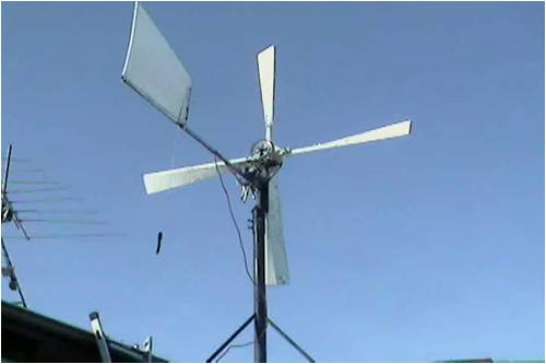
Also you would never ever use a vane for directional control!...at prop sizes like 16 feet.
I should have left the same Saginaw arm up there as I had it the week before I took this picture...
it was also from my ex 10 foot C-band Satellite dish.
That's what I used to turn it out of the wind, when I wanted to "stop the prop"...
it gave me a swing of 170 degrees and my prevailing winds here are from 280 to 060 degrees.
But after I let it free wheel in wind speeds at 100 kmh+ and at temperatures of -45 Celsius I am not concerned
about prop stopping in high winds any longer.
We don't get Tornadoes here and if we do, that prop will be my least concern.
About the wider tips:
If I don't like these, they are easy trimmed to look like
any conventional wind mill prop with a simple jig saw cut.
I did not only try this already but also tried all sorts of other props, like the "air foil" profile, the "PVC Pipe" taper cut etc etc...well You know what is published about wind mill props on the internet as well as I do.
With the 16 footer I will stick by my guns and stick to the no taper=constant width from root to tip, like on a Herc prop.---because it does give you a lot more power ....I did actually test and measure the difference.
My blades are not low speed because "of the drag at the tips" either...they are low speed high torque because of the pitch I have chosen very deliberately so that I get approximately 1 revolution per second per 10 kmh wind speed increment (and zero loading of course)...
and that was simply to expedite the data logging.
...and in anticipation that a 16 foot blade would break the sound barrier if I were to use the prop designs posted on the internet for these little 8 footers.
So with a 16 footer you do have to use gearing just like they have to use gearing in a commercial turbine.
Then you can say "the fact that you have to use gearing...."
Also with the 16 footer I will have to use my Saginaw arm again...only a fool would allow a weather vane to
make undesirable momentary directional changes with that prop size at full rpm.
Back to the "twist"---the pitch variation per root-tip distance that is the only way to make an efficient turbine blade.
I wonder if some of the people who publish their "air foil" prop designs ever considered that an airfoil is in a stalled condition when the a.o.a. (angle of attack) to the relative wind exceeds the "Reynolds" number of their airfoil.
"a.o.a" can get critical already at 15 degrees!
Most airfoils are in a full blown stall condition at around 22 degrees.
Think about it, how fast these kinds of wind mills have to turn and are aerodynamically in a stall condition before the actually come out of this >22 degree relative air flow direction condition!!!!
Of course "start-up cogging" is then a big problem!
But to each his own...No I am not a wind mill guru but I did experiment a lot.
That "Herc" I showed you did not go anywhere for a whole month.
One of the props wound up in our so called "Millionaires dump" up there...believe it or not there are even Helicopters in that dump!
And we did experiment up there with all kinds of props and all kinds of generators, just to pass the time.
I must say, the "Herc" prop was the best damn wind mill
I had ever laid my hands on!
Just one more thing about the other guy with the 2,3,4 blade option and "follow the money trail" logic.
2 blades are a poor choice, because once you go through all the trouble making a stand, hub, shaft + generator
you might as well grab with 3 blades whatever comes at you.
and about the "money trail logic"....did you ever consider the cost per blade when you go into that size where you have to use a 80 foot flat bed to haul it?
That is simply a cost versus amortizing accounting decision....not an engineering decision!
But like I said...You do it your way, I stick by mine.
It was not my intention to "out-do" anybody here...
but rather to share my experiences...nothing more!
I can see now, that was a mistake...
My best greetings to You all from Canada.
So long!
Edited by Bernhard 2010-02-04
Downwind Guru Joined: 09/09/2009 Location: AustraliaPosts: 2333
Posted: 06:31am 03 Feb 2010
Copy link to clipboard
Print this post
Bernhard
Mate! i am not trying to pick an argument with you about your design, just merely trying to point out there is many reasons to not go to the extent of design you have.
It would seem you are building a generator to suit the blades, most would build the blades to suit the generator.
You must be trying for some large Kw's to go to a 16 foot set of blades or the blade design is not optium for the generator.
It is interesting to see what and how others do things and be a boring forum if these things were not discussed.
Considering for years and 1000s of builds your design has not been adapted, should imply there is a reason why?
And i can ensure you it has been tried and tested before.
I see a blade design in 3 sections ... startup...cutin...and stall... all 3 sections is important to a design to get good operation and retain control of the mill.
As you say each to their own.
Please keep us up dated on your developments as there is always something to learn from others, for better or worst.
Can i ask you to refrain from posting full quotes of previous postings as the whole idea of a thread is to be able look back on the previous post from another.
If you want to address me in a post than "Downwind" is enough.
Why clag up cyber space with repeats.
Pete. Sometimes it just works
Bernhard Newbie Joined: 01/02/2010 Location: CanadaPosts: 12
Posted: 07:41am 03 Feb 2010
Copy link to clipboard
Print this post
No, I did not perceive YOUR reply "as picking a fight"
About the Kw's...no I am not going to build a toy or a hobby wind turbine.
and what do you mean by "my design"?
Is that the pitch change from root to toe?
Any full scale commercial turbine has exactly that!
Is it the gearing, because hi torque low rpm works better
than hi rpm at the prop shaft ( on a large scale turbine)?
Can`t be that either, because any large turbine does that too!
Have you ever been up in the power house of a commercial wind turbine?
I have!...and there is a huge transmission!
So, so far I can`t see where I am the only one out of
thousands who does it "my" way.
Is it the blade being as wide at the tip as at the root?
Maybe out of thousands of builders I am indeed the only one there...but I did measure the difference.
And as far as that blade width and 3 versus 4 blade theory goes...I can kill these 2 flies with one stone:
Try this:
Neither you nor I have a wind tunnel to settle this, but
you can hang a string duplicate of exactly the same length with exactly the same weight at the end...
One in front of your prop and one behind.
Make sure you hang the one behind, so you can shift position from tip to center to compare all area behind the prop....center to outside arc of your prop.
If you encounter optimum wind conditions put a load on your generator/and or alternator and vary it.
If the string behind your turbine still dangles at almost the same angle as the one in front as the load is increased and does so in almost every position...then your 3 bladed mill is not doing too good when compared to a 4 "blader".
the 3 versus 4 on the large commercial mills is strictly a cost/benefit decision...not an engineering decision.
The 2 strings can show you that in one glance!
The math to find out how much kinetic energy you "stole" from the wind using the 2 string "d-angle" difference is
not all that complicated...but You don`t even need it.
You can just calibrate the angle against airflow and use your chart...is in the end more accurate anyway!
That is, if you do not just want to know how many watts you got total, but which zone of your prop contributed the most to this total.
So that it doesn`t dangle too much...a fly fishing lure on a short string works good for me.
Edit=add some pictures.
This is about the myth, that wide tips create drag:
See, the rotors are root to tip same width.
On the Russian MI12 even wider at the tip.
The idea of narrowing the tip on a large commercial wind turbine is again cost cutting.
Wide tips result in higher structural loads and consequently require more strength at the root of the
blade...again, its an accounting decision and has nothing to do with aerodynamic efficiency!
Helicopters "auto rotate" in "wind mill mode" rather well. Would they not most pilots would refuse to fly one that can't!
And the 4 blade = inferior?
Maybe the Navy&CIA are both stupid then, that's their "black" version...ultra quiet, tips also as wide as the root and 4 blades. Edited by Bernhard 2010-02-04
oztules Guru Joined: 26/07/2007 Location: AustraliaPosts: 1686
Posted: 09:45am 03 Feb 2010
Copy link to clipboard
Print this post
[quote]Actually I don't "require" gearing, but use it so I can test all sorts of alternators/generators at all sorts
of wind conditions and data log them.
This is only my test rig...
It (the gearing)did allow me to run an 80 amp alternator from as used on a 600 hp Volvo Diesel.
I don`t think your mill can turn at 2100 rpm, that's the typical "cut in" rpm of "automotive" alternators.
My Prop with gearing worked just fine and had I wanted to I could have "smoked" this alternator any time I wanted to...again, my prop "with the drag on the tips" did just fine, thank you![/quote]
No my mill can't turn at 2100 rpm... it can make over 5000 watts at 400 rpm.... thats near 500 amps in 12v terms.... but we'll get to that soon enough.
Your 80 amp truck alternator is not much more than an amusement in wind power terms... and here's why.
I think you have been operating in an information void.. on your own. You have achieved much on your own, and displayed some novel engineering.... your proud of it ..... and you should be.........but the cruel facts are these:
[quote]My blades are not low speed because "of the drag at the tips" either...they are low speed high torque because of the pitch I have chosen very deliberately so that I get approximately 1 revolution per second per 10 kmh wind speed increment (and zero loading of course)...
and that was simply to expedite the data logging.[/quote]
This gives us some data on your device. Your TSR is below TSR <2. With 10:1 gearing you get to alternator cut in. This would need to be about 30 mph. Power at the shaft should be around the 2000w mark. If your blades were as efficient as you think, they would already be in a position to overpower your volvo 2:1. The volvo can only do 1000 watts or so.
To get above the cut in to drive the battery load hard will require a hundred more revs perhaps. The wind would be now blowing through the blades at near 42mph to achieve this. The shaft power now with normal blades would be nearly 6000w. If you could match the blades properly, thats >500 amps@12v...... I think your underestimating the power you have been working with.... 80 amps is easy if you use a decent alternator, and decent blades. You have no furling so these figures should be close.
What you thought were good figures, are not as good as you could do ... if you listened to the folks that have done it all before you.
Now I have pulled over 5000w @ about 32 mph. My TSR=6.5, and my rpm would have been just over 400rpm. Home built turbine.
Watts available would have been around 6500 (shaft watts), but my efficiency was falling... so only recovered a bit over 5000w. This was not into a battery load, but a resistive load. What it showed me was that my blade loading with batteries was very poor. I could only manage 3500w or so into batteries. My losses were greater than your volvo alternator in smoking mode.
Your blade theory needs overhauling, and alternator theory as well. If you believe that that is not so, no-one can help you improve.... and there is ample room to do so if you so choose.
16 footers are commonly built at home, and perform very well with the tail feather steering. Usually hit 7kw peaks, but run happily at 2kw or so.
If you build a 16 footer with decent blades, be aware that there will be about 15000 watts at the shaft in 35 mph winds.... thats over 1000A@14v .
And yes I play with a few mid size ones with gear box drive induction motors in them. Here is one of them here:
[quote]Is that the pitch change from root to toe?
Any full scale commercial turbine has exactly that!
Is it the gearing, because hi torque low rpm works better
than hi rpm at the prop shaft ( on a large scale turbine)?
Can`t be that either, because any large turbine does that too!
Have you ever been up in the power house of a commercial wind turbine?
I have!...and there is a huge transmission!
So, so far I can`t see where I am the only one out of
thousands who does it "my" way.[/quote]
Wrong again:
I do the electronics in them. They and their bigger brothers are high speed machines... not slow. They look slow, but their TSR is quite high. They use high speed lift profiles...... Their large diameter makes that translate to low rpm. If they used your TSR, they would turn very slowly... about 1/4 of what they currently do. Being an engineer, you can do the sums.... bigger they are slower they turn for the same wind speed. If the wind was 40 feet/second, your tips will be around 60 fps. These big boys will be around 280 feet per second.... it is just their tips describing a larger circle.
If you do some reading, you can come up to date with how the world has moved on from drag machines. There is nothing wrong with them, but to match the load to electricity generation, we need to get the best RPM we can usefully muster. As with all things, there is a sweet spot, and that seems to be about 5-7 TSR. Any higher and our torque suffers a bit too much, and much lower, the alternator begins to get to big and expensive to direct drive. Gearing up on smaller turbines is a losing game, on bigger machines it is easily dealt with with the immense power available. For a 50 meter monster there is over 1.3 million watts of shaft power (1700 HP)available at 33 mph (TSR 7 CP .3) It is doing about 40 rpm at this power level.
So plenty of horse power spare to drive the step up box for the induction motor. The newer ones may be direct drive neo designs.
[quote]the 3 versus 4 on the large commercial mills is strictly a cost/benefit decision...not an engineering decision[/quote]
This is just silly. Do the engineering on it. Don't just guess.
If you could get a few % improvement by supplying another lousy blade for a machine running 24/7 for 25 years, they would do it in a heart beat. They will do what works the best..... and they will all follow best practice or put another way....the investment companies will go with the most efficient..... the rest will perish.
I just don't understand why engineers have such trouble coming to terms with wind power.
Your choice to stick around and learn, or go solo and get what you think are great results. If you make remarks that can't be supported by physics or sensible experiment (yours are not, but you don't see why), you will get flack.... as will I.
A clue to youe test bed. Once you understand load matching, you will find you are only matching that blade set to that alternator nothing more, nothing less. This does not tell you which alternator is the best wind alternator, only which is best on that blade set for that voltage setup.
Eg. If I test mine on a 12 volt battery, I will struggle to get a few hundred watts. I could conclude that the system was junk... and try some thing else.... or be happy with 200 w.
If I just change the battery pack to 24v, I suddenly do a lot better, maybe get to 500W in the same winds. I could be happy?
Now I try it on an 80v battery, and suddenly it performs totally different. I can easily get 3-4000 watts.
Can you see that the test is meaningless if you don't know just what it is your testing? Just changing the load is the difference between 200 and 4000 watts. What did your tests really show you?..... and your prop tests??? were they loaded properly for each profile? Answer... NO. The Herc prop is rubbish for a windmill..... but if the loading is terrible, then the Grunt of a drag blade will conn you into thinking it is the winner.
The secret to it all is matching the load to the prop. Easy to do with high torque low rpm.... but usually poor results are normal as builders sacrifice power in all areas as they think it is easy. They soon are so far from ideal, they don't have a clue what they should be getting.
When you start to match low torque high rpm, you quickly learn how to match the load properly, or it just won't run.... your experiments perhaps. When you do finally match it, you blitz the low speed high torque designs.
Airplane and chopper blades are also useless to use as analogies. They are doing the opposite job to the blades we need. If you can't see that then all is lost.
..........oztules
Village idiot...or... just another hack out of his depth
GWatPE Senior Member Joined: 01/09/2006 Location: AustraliaPosts: 2127
Posted: 11:27am 03 Feb 2010
Copy link to clipboard
Print this post
Hi Bernard,
Quite a lot has transpired today.
I think that if you look at the scale of things, large windmills are engineered for performance and for accounting. [maximum return on investment]. There would be no difference in transporting a 40m long tapered blade, to one that was constant chord. There are many engineering benefits with a tapered blade re lifetime expectancy. A windmill is usually located in difficult terrain, sometimes on tops of mountains, and is designed for a 25-30 year service life, with a prime requirement of no blade servicing if possible.
If you compare the service schedules and inspections necessary on heli blades and fixed wing planes propellors, and imposed this on a windmill, then there would be no windmills.
Engineering the blade the way we see, maybe even at the expense of possible slightly lower efficiency, but results in a unit that will last the distance without blades service. I would expect the forces on a constant chord 40m windmill blade would require almost solid carbon construction and regular checks. Engineering a tapered blade removes most of these issues, and allows almost conventional construction to be used, and without future inspections and testing.
PS: It looks like the tip blade pitch angle on you 4 blade mill is around 40deg. This gives approx loaded TSR of 1. Can you confirm the angle? Your windmill 2.4m, say, 7.5m rotor arc circumference, should spin at approx 1rps, or 60rpm, in 7.5m/s winds, unloaded. Gearing is essential, as it is hard to make power at these rpm wothout it.
PPS: I see oztules has pipped me to the post. He has first hand experience, working on these commercial units, and as he says, the bottom line is return on investment. If they could gain a fraction of a percent efficiency, we should see windmills the way you describe, but we don't.
PPPS: I have built my own systems, including blades and alternator. Small scale of course, 1000W, well behaved, 3m rotor. I started off with a single blade design, and ended with 3 blades. 4 blades suffer similar harmonic problems to 2 blades. I was restricted to direct drive, so higher rpm was the prime goal.
PPPPS: I don't think there is much point in comparing driven blades and windmill blades, as each needs to be designed for different purposes. I have a propellor from a light plane. Looks good, but is useless as a windmill blade.
If the blades you are using work well enough for you, this is fine, but readers should be aware that the low tsr blades necessitate either a larger alternator, or gearing. One is wasteful of materials, and the other compromises mechanical efficiency.
There however are applications where low tsr and high torque are still used, as in water pumping applications. It turns out that a lot of these water pumpers are now being replaced with electric windmills and submersible electric pumps.
I hope you get to test and confirm much of the advice given. BTW, this thread has drifted a fair way from the topic now.
Gordon.
become more energy aware
KarlJ Guru Joined: 19/05/2008 Location: AustraliaPosts: 1178
Posted: 11:34am 03 Feb 2010
Copy link to clipboard
Print this post
OK, my turn to chime in.
The extruded blades we have available to use are constant profile blades that work well.
Note super twist / taper is not really necessary for a high performance blade as you point out
but i'm sure it helps.
I have an Airline Transport Pilots license and here are some observations I made during flying these A/C
fixed and rotary wing with 2, 3 and 4 bladed props and two and three bladed rotors
Navajo- 2 bladed prop goes fast but doesnt climb well.
Navajo- 3 bladed props goes fast and climbs well
Navajo- 4 bladed props goes slow and clims like hell.
Why? -to be honest I have no idea and the "testing" was merely an observation I made on otherwise similar aircraft with 310hp per side weight was similar too at Max take off weight every day (freight run)
Now for the choppers, being the mechanic I balanced blades for our Jetranger -perfectly! but in flight during turns you can FEEL the stick kick back with the rotor rpm However in a Eurocopter 3 blades there was nothing like that stick shake
as for the Hughies 500 well that sucker was smooth as with 5 blades (but noisy inside as transmission over your shoulder)
This is because when the blades are out the side of the helicopter they are doing all the work but out front doing nothing for the roll (swash plate changes the pitch as they go around), with more than 2 blades it is smoother to fly.
Aircraft with reversing props (turboprops driven by gas turbines) you'll notice horrible noises when blades are run in reverse pitch -airfoil not optimised for this condition but works well enough.
This is where I think you are at
-works well enough but not optimised.
Coming from the aircraft industry I have a few words of wisdom- Aircraft stuff and windmills are a fair leap, the guys such as OZ and Gordon and Pete and Phill etc etc
are right up there with the hugh Piggots of the world if you ask me, they have the runs on the board.
No-one is criticising your efforts, just steering you in a better "matched" direction to get some more grunt for free.
Its all a learning curve, and with some luck you're learning lots.
I like the can do approach and so do the boys with the expertise, thats why they are here, to help guys like usLuck favours the well prepared
A joke (or a moral).
Burnie Hard and his missus (from Texas) were on a "discover the ancestors" pilgramige to Ireland.
A distant relative was their host for the tour.
This particular day the host invited Burnie (and his missus) to a car trip up to his cousin's farm .
Upon seeing the car Burnie exclaimed " you call this a car ? Why back in Texas we have cars so big you could put this thing in their trunk !" ( "boot" for you poms).
The host bit his tongue and said nothing.
Upon arriving at the farm Burnie asked "how big is this spread ?", to which the reply was "oh about 50 acres".
"Fifty acres ?" exclaimed Burnie, " man - back in Texas we have cattle yards bigger than 50 acres !
Again the host bit his tongue - and proceeded to take them over to the veggie patch.
"These are potatoes that we grow here in Ireland " the host explained , showing Burnie (and his missus) some "fist sized" spuds he had just forked out of the ground.
"PTaters ? You call them PTaters ?" asked Burnie in disbelief. " Hell - back in Texas we grow PTaters the size of water mellons !"
At this point the host's temper got the better of him and he replied " Burnie that may be so - but here in Ireland we grow potatoes to fit our own mouths!"
Sorry folks. As I said a joke or a moral. Take it as you like " cause I don't give a s%$# ".
The main reason for more than 2 blades on a rotary wing aircraft is to increase lift and at the same time keep the tip speed below the speed of sound (rotation speed + forward speed) on the leading side.Jack


 I think I would have a little trouble getting past customs with my M14 though.

 ..... but if your making the mill for powering your home, it is not the path to follow. It will cost you more diesel for the batteries than necessary.