
|
|
Forum Index : Windmills : steel hubs
| Author | Message | ||||
| dwyer Guru Joined: 19/09/2005 Location: AustraliaPosts: 575 |
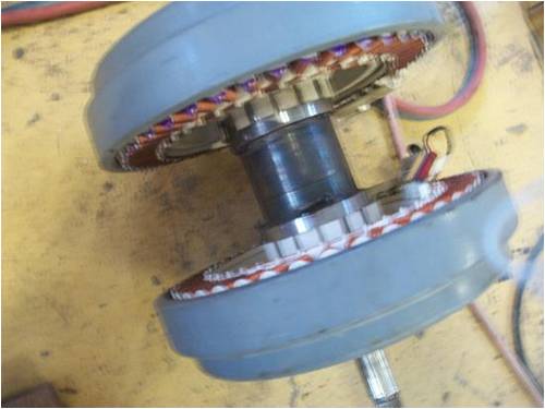
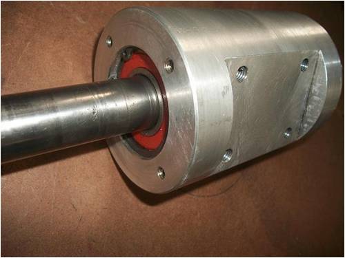
hi guy I have just finished working on my project which is a steel hub and the next one will be an aluminium hub which is still on the drawing board. It will hopefully be on sale in the next fews weeks and it is easily assembled for anyone who would like to build a fisher and paykal windmil instead of useing a plastic hub. There are some photoes of my steel hub and would like to recieve some feedback on these hubs.note all hubs bearing size will 25mm x 15 x 52 mm .but Glenn i cant' down load the numbers of photoe as file is excess 500 kb need your help ? 
Dwyer the bushman |
||||
Downwind Guru Joined: 09/09/2009 Location: AustraliaPosts: 2333 |
Hi Dwyer, I gave a quick ...how to shrink a photo on another thread a few days ago Have a look HERE on page 2. See if that helps Pete. Sometimes it just works |
||||
| dwyer Guru Joined: 19/09/2005 Location: AustraliaPosts: 575 |

Many Thank to Downwind for right direction is long time ago since l have download the pictures |
||||
KarlJ Guru Joined: 19/05/2008 Location: AustraliaPosts: 1178 |
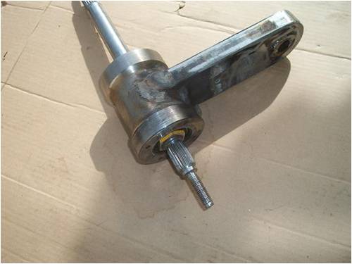
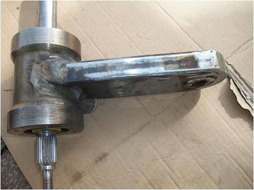
another version of PhillM's arm! He should have patented it!! does it run the stock F&P bearings? Devil is in the detail, some kind of indexing is a good idea, as fully mounted up with the prop and tightening the Massive Nut is quite a challenge as the motor assembly and prop add up to quite a weight. Looks like your offset bar is hollow section, problem i see here is getting the sleeve flat with the remaining surface as when you bolt this to the turbine head assembly having a large flat area is a winner. without it i think given some time the sleeve will break out of the box section, the bolt needs to be BLOODY TIGHT. making this bit shown is piss easy, even with 90-100mm box section the plastic bearing can be easily mounted, add an 8-10mm piece of flat stock and done. Drilling the hole up the guts of no2 stator is not easy either. Luck favours the well prepared |
||||
| dwyer Guru Joined: 19/09/2005 Location: AustraliaPosts: 575 |
Hi karl Little bit of phill's arm, however it has 2 bearings on this: 25mm x 16 mm x 52 mm,and 25mm x 12mm x 47mm has a cicular clip fitted only making this hub once as a personal project and no more as i will then make an aluminium hub that mantains a different design with two bigger bearings, one keyway for second stator and no arm. Anyway five aluminiun hubs will be ready in next couple of weeks Regard Ian 
|
||||
MacGyver Guru Joined: 12/05/2009 Location: United StatesPosts: 1329 |
Just a thought, but maybe you could make the aluminum one a casting. Someone here on the 4m (Trev?) does aluminum castings and perhaps that could save you lots of machining. . . . . . Mac Nothing difficult is ever easy! Perhaps better stated in the words of Morgan Freeman, "Where there is no struggle, there is no progress!" Copeville, Texas |
||||
| KarlJ Guru Joined: 19/05/2008 Location: AustraliaPosts: 1178 |
blade mount? Luck favours the well prepared |
||||
| dwyer Guru Joined: 19/09/2005 Location: AustraliaPosts: 575 |
hi Mac Mac said that aluminum castings and perhaps that could save you lots of machining. Well not really the time and cost is almost the same as l will working on CNC machine is quicker to work on than my 48 mm bore lathe however Aluminum casting will be cheaper if l make 500 hubs as l have done my homework Regard ian 
|
||||
| dwyer Guru Joined: 19/09/2005 Location: AustraliaPosts: 575 |
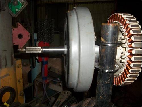
hi everyone I just finish my first F&P Aluminium dual bearing assembly, has large bearing fitted 25mmx52mmx17mm, hopfully will be up for sale soon. Hope you all enjoyed my ideas and my workship. 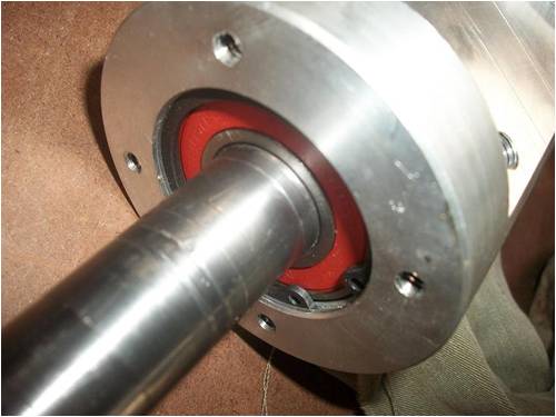
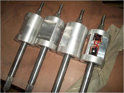
I am getting too tired to say anymore Good night to all kind regard ian dwyer |
||||
| Downwind Guru Joined: 09/09/2009 Location: AustraliaPosts: 2333 |
Nice machine work Ian. Will the bigger bearing help to reduce or increase the bearing drag. One advantage with the ally is, it will keep the weight down for postage, if the shaft was supplied by the buyer. How do you fix the second magnet hub to the shaft. Will you be offering a blade hub as well to fit the spline. I like your work its simple but effective and easy to adapt to any mounting. 
Pete. Sometimes it just works |
||||
fillm Guru Joined: 10/02/2007 Location: AustraliaPosts: 730 |
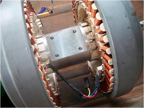
Hi Ian , Nice machining and milling work there , I notice you seem to be using the plastic fingers as the stator to rotor alignment method instead of the bearing retainer in the stator that usually does the aligning or is there another spigot to get correct alignmemt ? PhillM ...Oz Wind Engineering..Wind Turbine Kits 500W - 5000W ~ F&P Dual Kits ~ GOE222Blades- Voltage Control Parts ------- Tower kits |
||||
| dwyer Guru Joined: 19/09/2005 Location: AustraliaPosts: 575 |
hi Pete and phill I will explaining more detail tomorrow as at the momest i am working on other job soon l get time will get back to you regard ian |
||||
| GWatPE Senior Member Joined: 01/09/2006 Location: AustraliaPosts: 2127 |
The F&P unit I had, used the plastic fingers that fitted the tub moulding, to align the stator on the bearing hub. My 100S stator was quite old, and the plastic fingers were brittle. Some had cracked. I was able to repair it with some carbon fibre, but I had to file away some of the poles, as it was no longer symetric. The alignment technique on the original unit seems to be a more precise method. Gordon. become more energy aware |
||||
| KarlJ Guru Joined: 19/05/2008 Location: AustraliaPosts: 1178 |
i just used the original bearing for alignment. the fingers on the stators i broke off intentionally, look much smoother without them and they dont do anything as the bearing is what is maintaining the stator alignment. This could be a real headache for this design that I didnt consider. That said its very nicely done and every design has some teething issues. Really need the next bits for us to look at too, particularly the prop mounting solution which is most peoples major difficulty, they get to this bit and abandon. I would like to see someone get 100 laser/water cut splines and a simple hub for sale. I have played with Trev's aluminium design for the extruded blades but it has some inherant problems for the amateur in that if the holes aren't drilled exactly through the lot at the right angles then its a scrap and replace fix for the tubes at least. This can turn into a bit of a mess quickly. Luck favours the well prepared |
||||
| dwyer Guru Joined: 19/09/2005 Location: AustraliaPosts: 575 |
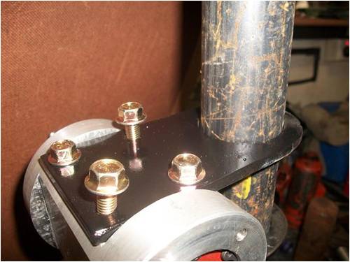
hi everyone l don;t much problem with alightment stator as bearing housing are well fit as l am aware of before however there is other way of ajustment by undone the 4 bolts as you see the photo 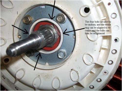
Also made up some steel bracket and give you some ideas what l am doing in my crazy mind  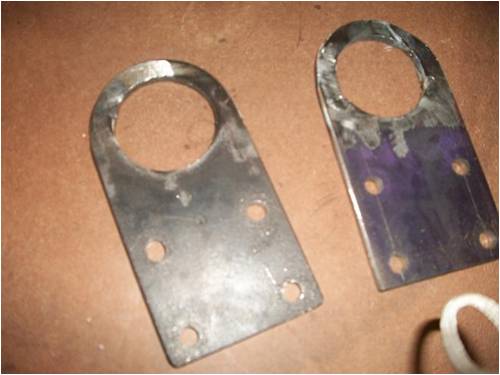
and heavy wall pipe 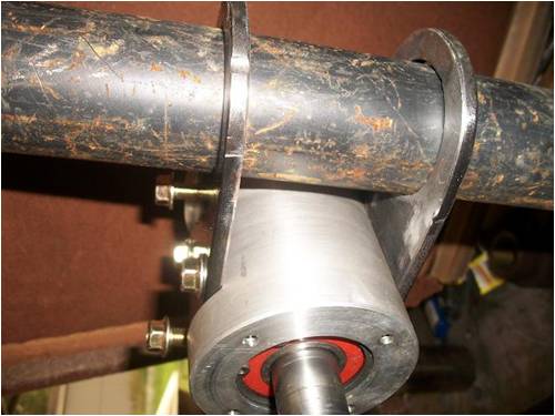
 if you want to give me feedback on my design feel free to comment. hope you like it.and also will be up for sale in later date if you want to give me feedback on my design feel free to comment. hope you like it.and also will be up for sale in later date
cheero from ian dwyer |
||||
| brucedownunder2 Guru Joined: 14/09/2005 Location: AustraliaPosts: 1548 |
Ian came to my place the other day . His machining is 1st class . nice work . He has some very good ideas ,so I'd recommend his work to you all. Bruce Bushboy |
||||
| MacGyver Guru Joined: 12/05/2009 Location: United StatesPosts: 1329 |
dwyer Just curious; how do you draw black arrows on a picture? I see you've successfully done that in your first picture and I'd like to know how you did it. Thanks. . . . . . Mac Nothing difficult is ever easy! Perhaps better stated in the words of Morgan Freeman, "Where there is no struggle, there is no progress!" Copeville, Texas |
||||
| Downwind Guru Joined: 09/09/2009 Location: AustraliaPosts: 2333 |
Mac, If you resize your photos in PAINT then you can add the arrows and boxes to the imiage while in paint then save the changed imiage. It is worth having a play to get use to it. Pete. Sometimes it just works |
||||
| KarlJ Guru Joined: 19/05/2008 Location: AustraliaPosts: 1178 |
some tilt back of the lot to give some better clearance from blades to the tower may be in order depending on the type of blade you decide to use. I also reckon Phills idea of having the bearing assembly adjustable so furling can be played with is a big winner, beats the hell out of adding weight to the tail or worse still trying to add lightness.... Looks bulletproof and heavy though which is always a winner. Phillm machine weighs in at best part of 50KG albeit the prop pushing 20KG on its own. Lastly, cant recommend the Aluminium blades highly enough, i've read heaps about the various blades on the market and to have the startup torque they do and the top end to boot turns into a high performance mill. Luck favours the well prepared |
||||
| KarlJ Guru Joined: 19/05/2008 Location: AustraliaPosts: 1178 |
Oops lastly, the 4 bolts may not be a relaible method of locating it as they dont actually do up 100% tight, the tabs on the metal rings or shoulders on the ones with round holes (two different types depending on the age of the stator, punched with tabs or round holes with spacer attached to one of the rings) thus even when they appear tight its possible that the stator will still move, I had this problem as previously stated Phills design doesnt use the fingers on the stator/hub thus my perfect alignment of the two stators to reduce cogging didnt work for long. I came up with another solution to stop them rotating (although wouldnt be a problem as they cant rotate far, and at least they are always in the centre) Luck favours the well prepared |
||||
| The Back Shed's forum code is written, and hosted, in Australia. | © JAQ Software 2026 |
