
|
|
Forum Index : Windmills : Left over parts from 7 phase conversion
| Author | Message | ||||
PPGFlyer68 Newbie Joined: 18/03/2010 Location: United StatesPosts: 4 |
Howdy Ya'll, So now that you all have done the cog-less, 7 phase conversions to your F&P motors, ie... combining the rotor (48 pole magnet ring) from a 36 pole stator with the 42 pole stator. and yes, it works wonderfully, what to do with the left over parts, ie... the rotor (56 pole magnet ring) from the 42 pole stator and the 36 pole stator...well, here is an idea. I did the math and the computing and came up with an even less cogging, 9 phase conversion. I also made it so it is possible to go from being a 1x4c to 2x2c. Just like you would do for the 7 phase conversion, divide the stator (36 pole) up into 4 sets of 9 poles. 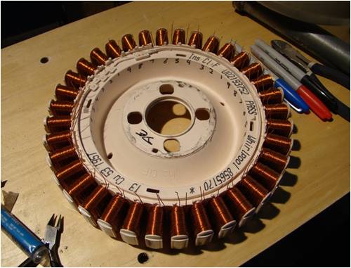
unfortunately, unwinding each coil one turn will not reach to the 10th pole like you would do with the 7 phase conversion,(except you stretch it to the 8th pole for that), so with that being said, go ahead and rewire the stator, but dont go all the way around, only wire the first 9 poles to the second 9 poles, then rewire the 3rd set to the 4th set 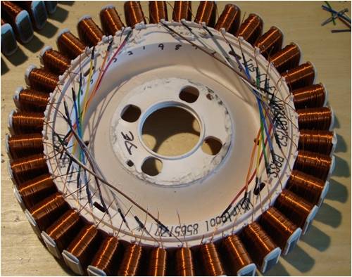
now that you have 2 sets of 2 pole sets in 9 phases, between the 2 sets, wire and solder in a 9pin connector, i used a 9 pin dip connector. 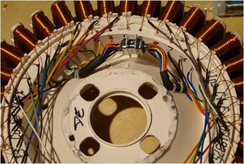
now, on one half, bring all the commons together(the black wires on the left side in the pic) and solder them to another 9 pin with long enough leads to reach up and connect to the other half's 9 pin connector. be sure to use the same pin set (male or female) as the other end of that half of the stator. also be sure to ground them all together as this becomes your master common for all the coils in the stator, be it configured for 2x2c or for 1x4c 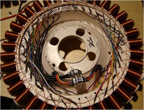
this is going to allow you to switch the motor from 2x2c to 1x4c. now you get to finish up by connecting the last set to 2 9 pin connectors, one to connect to the other half of the stator and the other as your power output. 
if you notice in the picture, the last set of wires go through the plastic housing, as it does, the wires coming from the last set of coils is soldered to them as one end runs up to a 9 pin connector to be connected to the other half of the stator, the other end is your power out from the now generator stator 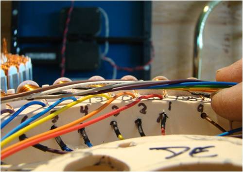
now this conversion process is a bit complicated and even i have to sometimes stop and analyze the wiring and connectors to ensure i am connecting them correctly. To go from 2x2c to 1x4c, the "common" plug should already be plugged into the beginning side of the second half of the stator (or set 3 in) and the other 2 connectors SHOULD be connected together. Disconnect both sets of connectors and connect ONLY the "set 2 out" and the "set 3 in" and leave the other 2 connectors disconnected. 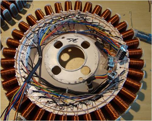
have fun with this if you decide to do it, i now have and additional generator. it will be interesting to see what kind of replies i get from you all. when the winds are calm, go flying |
||||
| Gizmo Admin Group Joined: 05/06/2004 Location: AustraliaPosts: 5187 |
Wow. Fantastic work. I'll need to get my head around it, but it should work fine and like you say, you end up with two cogless alternators. Glenn The best time to plant a tree was twenty years ago, the second best time is right now. JAQ |
||||
KarlJ Guru Joined: 19/05/2008 Location: AustraliaPosts: 1178 |
FARQ...complicated, i have no idea how you worked it out that it will work but i trust you. the question now is what does it suit? 12/24/48V and given 9 phases wont you have some running almost parallel in the star -thus not producing much output 3phases 120deg apart 9 phases =40 deg apart my electrical theory ends there ... Next ..TESTING going to need 5 bridge recs mmmmm 5x$5 =more expensive than the F&P bits but that said I still admire the brain power it took to create the monster. guess you being a USA guy this was necessary as they are rare and making 2/2 wins over. to be totally honest, a quick twist of the poles and a dual stator, there is almost no cogg anyway. Luck favours the well prepared |
||||
| PPGFlyer68 Newbie Joined: 18/03/2010 Location: United StatesPosts: 4 |
as far as the rectification, if you already have a 7 phase converted 42 pole stator, then you would only need to add one more bridge rectifier. and for the phase separation, doesnt matter, consider that each phase is like a single generator by its self, they dont conflict with each other due to the bridge rectifier. its like adding batteries in parallel to a light. this little experiment was brought on by my converting my 42 pole stator to 7 phase and having the left over parts, as you know, to do the 7 phase conversion you combine the rotor from a 36 pole motor (48 segment magnet ring) with the 42 pole stator, that comes with a 56 segment magnet ring rotor.... so what do you have left,.... a 36 pole stator and a 56 segment rotor.... this is just a way you can combine them and put them to good use.... ie. another generator. with what i have done with the 9 pin dip connectors allows me to change this new generator from a low volt/ high amp generator to a lower amp / higher volt generator. havent been able to do any real testing with it other than put a 50w 12v halogen lamp to it and hand cranking it to light it up... it works pretty well .... and no cogging either.... i would imagine most would just rewire this to be just a straight 1x4c so that low revs would produce the most voltage, but if you had high enough winds and was able to get er to spin fast enough, having it wired 2x2c you would get considerably more amps out. just some food for thought, and a way of using spare/leftover parts when the winds are calm, go flying |
||||
| KarlJ Guru Joined: 19/05/2008 Location: AustraliaPosts: 1178 |
Dont get me wrong i think this is an excellent idea but you need separate rectifiers for each stator or the parallelling of the two stators will cause it to electrically brake itself. and any kind of voltage doubler is out of the question too as it would be spectacularly complicated. -Pretty decent circuit to start with at 24caps and 12 recs for the two stators once you talk 16phases instead of 6 starts getting pretty messy BTW 2 stators =2.6-3.0m rotor thus cogging is a non event, mine starts up in 2m/s. the key in the F&P is wiring it to match the speed of your rig and the voltage you require, no good getting 48V at 50rpm and a max of 150W when there is 500-800W to be had if its set up right. food for thought again not knocking the idea I just like KISS principle better. Luck favours the well prepared |
||||
| PPGFlyer68 Newbie Joined: 18/03/2010 Location: United StatesPosts: 4 |
Karl, thanks for your input on this, but im not quite following you, "2 stators"?,"16 phases"? where did that come from? im not trying to knock your knowledge, im sure youre more experienced at this than i am. i was just coming up with a way to use the left over parts i had when i did my 7 phase conversion on my 42pole stator. now that i have a 9phase, i can go about building another windmill thanks again, you guys are the best  when the winds are calm, go flying |
||||
| GWatPE Senior Member Joined: 01/09/2006 Location: AustraliaPosts: 2127 |
I think what Karl was referring to was one stator has 7phases, and the other stator has 9phases. 9+7=16. Each phase will require separate rectifiers, as they will not be able to be parallelled on the AC. Would also be a pain for load matching with caps, with all the phases. The path of reduced cogging is well covered with twisting poles. There will still be iron drag proportional to rpm with either cogless, or twisted poles though. The best method will be determined by the wind reigime where the mill will be located. Sustained high winds will favour coggless, but then a slightly cogged mill will still be OK. In light, and turbulent conditions, a twisted pole unit with caps could still be a better option. Gordon. become more energy aware |
||||
| PPGFlyer68 Newbie Joined: 18/03/2010 Location: United StatesPosts: 4 |
OHHhhhh i see, well, im not adding it to my already existing wind mill, i will build a second one to use it on. and you are right about that on the phase matching. wouldnt work, post rectification would.... sort of... if the voltages were the same.. but i dont think they would be... so a separate windmill it shall be. when the winds are calm, go flying |
||||
| KarlJ Guru Joined: 19/05/2008 Location: AustraliaPosts: 1178 |
PPG having the two alternators different is not a bad thing. it enables better matching of the wind to generator output. For example a 24V F&P say 7X2C will make x volts at y rpm a 2X7C will make the voltage at much lower rpm but will be current limited earlier (by the windings) so.... what alot of us do is a combination on the one mill I run an 80S in 2X7C STAR for 48V and a 100S 1X14C in DELTA now here's where the advantage comes in the 80S in star will only ever make 300 perhaps 350W but the delta wired unit will top out at 800W drawback here is without caps the delta wired 100S wont make the 55v required for charging until 400rpm. without the 2nd stator for the low end it would be useless the 80S in 2X7C gives cutin of 160 rpm. and will top out (not make any additional power) at say 500rpm. thus what you have now is a mill which matches the power available in the wind better. SO my tip is to use both on the same mill, set one up for a low cutin and the other for a higher cutin that way your mill stays in control better as once the F&P becomes saturated (amp turns is the problem) the mill can run away and the furling needs to be spot on. by using the two stators you have a much better match. SO how do we work it all out? pretty much trial and error which is the beauty of the F&P, before there were 100 possible combinations now with your 9 phase unit there are 101!!! What works for one of us well, may not work for someone elses site and a different stator or rewire would be the order of the day. Karl Luck favours the well prepared |
||||
| The Back Shed's forum code is written, and hosted, in Australia. | © JAQ Software 2026 |
