
|
|
Forum Index : Windmills : New Ax-Fx Layout
| Author | Message | ||||
MacGyver Guru Joined: 12/05/2009 Location: United StatesPosts: 1329 |
oztules I couldn't figure out how to post a picture in the PM, so here's the sketch: 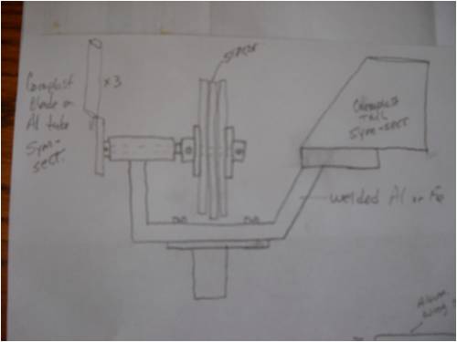
Sorry it's a little blurry. Also, disregard all the "notes to self" all over the thing along with the little bit of a picture at the lower right-hand side. I build R/C gliders and that mess in the corner is part of another sketch for a new plane I'm designing. Anyway, the basic windmill layout is a welded aluminum frame. A Delrin bushing will house the main shaft and the magnet wheels as well as the stator are the standard ax-fx design. Blades as well as the tail fin are being manufactured out of coroplast (corofute to some) plastic. The blades are one meter long with an aluminum spar and will weigh in at around 12 ounces each. Both the tail and the blades are to be symmetrical section. I am not using any yaw gear as the thing is so light, I'm just not worried about over-speeding. This is an up-wind design. I will be installing "stops" at 180-degrees atop the tower to limit the rotational movement so as not to have to worry about tangled wires or having to use slip rings. The mill will have free rotation within these limits and will be mounted to face the "typical" source-direction for my area. I'll do a complete step-by-step tutorial with pictures as I build it, posting my progress here on the 4m and a You-Tube video when it's flying. It'll be a while, so if you're a part of the "hide and watch" crew, make sure your cookie jar is full! Edit: typo . . . . . Mac Nothing difficult is ever easy! Perhaps better stated in the words of Morgan Freeman, "Where there is no struggle, there is no progress!" Copeville, Texas |
||||
| Perry Senior Member Joined: 19/11/2009 Location: Posts: 190 |
MacGyver, Looks like it would work just fine but a few comments. -You won't have any means of furling. 2m rotor is pushing the limits of a turbine with no overspeed protection. -You'll need to mount that stator to something. Should be easy enough to tie it to your main frame, you probably just didn't get around to putting it in your drawing. -Delrin bushing? Is that for your main bearing system? Bushings would be a non starter and you'll want some good tapered roller bearings. Cheap enough but a little extra work. Just some thoughts. Perry |
||||
97fishmt Regular Member Joined: 19/04/2010 Location: United StatesPosts: 77 |
Mac it sounds like too much work for a 2 meter turbine. If you are not worried about over speed then you must be thinking of just flat straight blades at and 5 degree angle or something with a tip speed ratio of about 4. If you are going to all the trouble to build an axle flux alternator you will want lift to get power out of it and you will need it to furl unless you don't mind it burning out. For a 2 meter machine you might be better off just finding a suitable motor and let her rip with no furling and a cheep prop. Been doing it for years for a close to the ground unit. |
||||
| MacGyver Guru Joined: 12/05/2009 Location: United StatesPosts: 1329 |
Crew Thanks for the comments, but I like to build stuff and especially like to build stuff from scratch. I design, build and fly R/C gliders and pretty-well know my way around wing design and aerodynamics. These "blades" will be made of 2 mm coroplast, which is similar to plastic cardboard only with square holes. In response to the "lift" comment, I've tried that and what I found is that as the speed of the rotor gets really high, the amount of lift created by say a Clark-Y wing section, will try to bend the blade. For that reason, I've decided to use a symmetrical-section design. I can build one of these blades in about 10 minutes start to finish (though that took a while to get good at!). The blades will be on the order of "high aspect-ratio" design and no wider than 3 inches at the root (inboard edge). When I said they'd weigh in at 12 ounces, that was a guess, but each blade will certainly weigh no more than 14 ounces. I'll weigh one when I put this thing together and show a picture of it on my mini electronic scale so folks can see its actual weight. As far as burning out my alternator, I plan on taking care of that with switching gear. Again, this windmill will be atop a very short tower (no more than 20 feet tall) and if the blade length becomes problematic, I'll just shorten it; easy! As far as building an ax-fx alternator being a lot of "trouble", relax. It's no trouble at all as have a great coach who lives on Flinders Island, Tazmania. There's nothing he can't fix and he's always willing to lend a hand. You know who you are, coach, and thank you in advance! [Quote=Perry]-Delrin bushing? Is that for your main bearing system? I'm a big believer in bushings. My motto has always been "simple is best". Bearings are dandy, but when they are sealed away and riding around in moist air, sooner than later they need attention, whereas a bushing just needs a squirt of diesel oil now and then. I use a steel shaft (painted where exposed to the weather) riding in a Derlin chunk, which I cut with a .0005 running fit using my lathe. So far, bushings have been far and away better than bearings when I've used bearings. Thanks for the comment though. Thanks again for all the comments. I'll post my progress as it happens. . . . . . Mac Nothing difficult is ever easy! Perhaps better stated in the words of Morgan Freeman, "Where there is no struggle, there is no progress!" Copeville, Texas |
||||
oztules Guru Joined: 26/07/2007 Location: AustraliaPosts: 1686 |
Looks like the basic layout is a fair design from this picture. Perry is correct, stator needs stabilization, and if you wish to use journals for bearings, then you will need to guarantee the thrust bearings/washers (or whatever you have in mind) will hold the rotor disks with well less than .25mm linear movement.... or you may interfere with the stator..... not pretty. Now it is a matter of building it, and finding out how many turns/coil you will need. From scratch is more fun for sure. Do you have a guestimate of the TSR of your chosen blade design? ...........oztules Ps, there are plenty of folks out there that know lots more than me with this stuff.... Perry for one..... he plays with real ones. Village idiot...or... just another hack out of his depth |
||||
| MacGyver Guru Joined: 12/05/2009 Location: United StatesPosts: 1329 |
[Quote=oztules]Do you have a guestimate of the TSR of your chosen blade design? Well, no. I have a free-wheeling (no load) mill in the back yard down below fence level, so the only wind it receives is an occasional gust here and there and when that happens, it screams! It goes scary fast in just a few mph wind (like 3!). Up in the wind flow, these blades "siren" in no time at all (especially if they are in close proximity to anything stationary, like the tower). I'll have to wait until I have a load attached to adjust length, width and pitch. The blades are made of 2mm "coroflute" plastic and are so simple to build, I can throw one together in just a couple of minutes. It's merely a matter of choosing the shape, making a fold and applying "ca" (cyanoacrylate) glue to the inside trailing edges. That goes off in a few seconds and it's a done deal. What takes time is pop-riveting the blade to the aluminum tube, which runs up between the sides and terminates about 7 inches from the tip. This early termination allows me to close off the end and make it taper down and look cool. The only down side to the "cool" look is it makes the tip kind of sharp. If it were to hit you at high speed, I'm sure it would do major damage (like cut off a limb)!! I'll be throwing up pictures as I do this build, so everyone can glean information for their own builds. And the part about each blade weighing in under a pound is absolutely true. A 3-foot "wing" section (from my planes) with a root of 8" tapered down to 5 at the tip weighs right at one pound. The plane wings use either a balsa or a thin basswood spar for support, but it only extends a few inches from the root up through the wing. The wing spar is used to bolt two wing halves together to maintain a 5-to-15 degree dihedral (for stability), since using a completely flat wing tempts tip stall at low speeds (take-off and landing -- each close to the ground!). I'm working on making an aluminum rod and tube design for this part, which will enable me to slide the wing halves together and secure them with a set screw. The tempered aluminum is extremely tough and light-weight to boot. It'll make a perfect dihedral keeper and wing joiner. A hollow coroflute wing or blade is extremely robust and would be nearly impossible to fold with wind alone. That's why I use them; strong and cheap! Nothing difficult is ever easy! Perhaps better stated in the words of Morgan Freeman, "Where there is no struggle, there is no progress!" Copeville, Texas |
||||
| GWatPE Senior Member Joined: 01/09/2006 Location: AustraliaPosts: 2127 |
Hi MacGyver, coro-plas is not what I would be making any wind turbine airfoil from. It is not that good for an aeroplane wing either. The only redeeming feature is crash survivability, but EPP foam is still a better option. Here is a pic of one of my own design gliders, I made in 2004. All hand made, including carbon/kevlar composite boom and fuselage. This is 1.8m span, and weighs in at around 400g, with all gear. The 1piece wing tapers from 10mm thick section at the root, to 3mm airfoil at the tips. The tail feathers are 3mm tapered to 2mm foam cored. All the black, is carbon fibre. The criss-cross surface spar system is now used by top commercial designs. 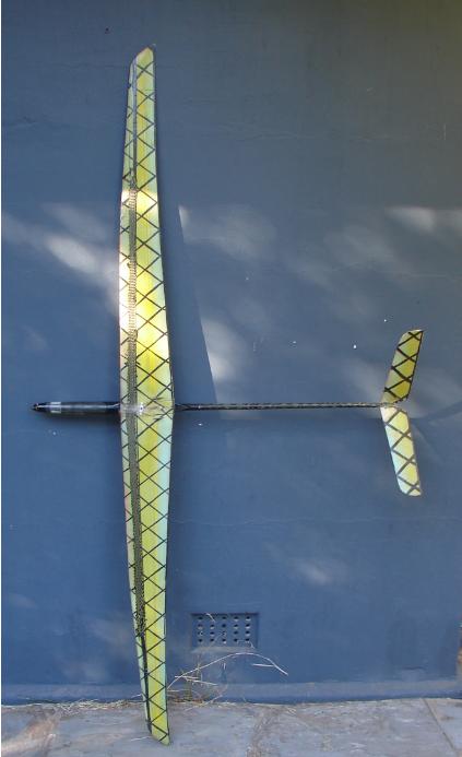
I tried making a foam core, carbon/glass bagged airfoil turbine blade in a similar fashion to these wings. Wood is better, and much cheaper for a turbine blade. Weight is not as critical a component. BTW, I was in at the start of discus launch HLG building. Gordon. become more energy aware |
||||
| VK4AYQ Guru Joined: 02/12/2009 Location: AustraliaPosts: 2539 |
Hi Mack if you must use delrin block as a bearing I would suggest making a ring oiler in it as you only need to add oil every few months. I have seen wooden block bearings with a ring oiler in old saw mills that where still working after 50 years. The core flute blades could be made stronger once formed by some of the expanding foam liquid used for flotation cells and insulation. Be sure to use a steel tube insert for the root out to at least 30% to take the torque as alum tube will fatigue quickly with the forces on the blades, and you don't want a sharp ended stuck in the top of your head, or worse someone else. All the best Bob Foolin Around |
||||
KarlJ Guru Joined: 19/05/2008 Location: AustraliaPosts: 1178 |
I agree with Gordon, I too have built lots of gliders, pylon racers and fun machines. The only thing I would use in the mill would be a similar design to the pylon racer or my southern sailplanes eclipse (a 3m glider) where I use carbon and glass for skins. Aluminium tube for the support is a bad idea, might as well use exhaust tubing. There are some serious forces and fatigue issues that a sailplane just doesnt see. a little movement here and there on a glider is no big deal but failure in a windmill application where loads are variable and continuous will break them in a matter of weeks. Plenty of experience with that here. If tules is helping out, cut some with a chainsaw and be done with it... Karl Luck favours the well prepared |
||||
| MacGyver Guru Joined: 12/05/2009 Location: United StatesPosts: 1329 |
Crew Well, by now you must have figured out I'm somewhat of a stick in the mud. I'm going to give it a go with the coroflute design anyway. I'll post my results good or bad. If the results are REALLY bad, I'll even post that; no sense in telling a fib, eh? For the past 40 years (give or take) I've used solid aluminum flat stock for my blades. They are very robust and I use a double-bolt arrangement to lock them to the hub, so they don't wiggle. I intend doing similarly using the coroflute, but using tubing instead of flat stock. I have decided to make the receiver (hub) solid, with the tubing sliding over a solid post, locked in place using three screws. One screw will use a slot in the tube to adjust the angle of attack and the other two will lock the tube down from one of three equally-spaced positions about the receiver stock. The screws will be machine-threaded into the hub stock. So far, all the blades / wings I've manufactured seem pretty hale and hearty. I'm counting on their extreme light-weight-ness (new word!) to be a big factor. Should work. Of course, I've said that a lot over the years; sometimes I'm right.  Nothing difficult is ever easy! Perhaps better stated in the words of Morgan Freeman, "Where there is no struggle, there is no progress!" Copeville, Texas |
||||
Downwind Guru Joined: 09/09/2009 Location: AustraliaPosts: 2333 |
Hi Mac, [quote]Should work. Of course, I've said that a lot over the years; sometimes I'm right. [/quote] Can you point me to which thread that was contained to. 
Only joking. 
Im not sure on the blade strength factor as with a glider it is not a fixed object and if the force gets great enough the whole glider can move in the air and not just rip a wing off, but with a mill its a fixed object so something has to give under force, if its not the mill moving then its the blades being the weakest link. I dont think there is any gain in light weight compared to strength. Strength is more important than fairys wings for blades that a good sneeze would distroy. But then you do like doing some things the hard way, so who am i to interfere with that route. Pete. Sometimes it just works |
||||
| MacGyver Guru Joined: 12/05/2009 Location: United StatesPosts: 1329 |
Pete I appreciate your concern along with everyone else's. You're all probably right and the thing will explode all over my neighborhood. I only hope I can get it on video like that big one that exploded in Norway or wherever it was. I saw it on You-Tube. I'm just enamored with the ease at which I can knock together a wing out of this coroflute stuff. I'll try working out a better method of attachment (to the hub) since that seems to be where all the concern stems from. I just have to make this work and work well; it's too cool to pass by. I suppose before I get too much time and $ into this, I should just move my backyard "toy" windmill up into the breeze, eh? Each of those blades is 30 inches and that's pretty close to 2 meters give or take. As it stands, when it gets into a little gust of wind (it's below fence level) it really cranks and starts to "whir" a bit. I can only imagine what it will do in a consistent breeze; I'll keep everyone posted on this. And you're right; I do tend to do stuff the hard way time and again. It's just a habit this late in the game! 
Gordon: I forgot to compliment you on as near-perfect a glider as I've ever seen. I pride myself in doing "neat" work, but your craft is exquisite! I like to crash stuff too much to be quite as elegant. You'd think after having flown R/Cs for over 30 years I'd grow up sooner or later, right? Not a chance; I'll still try an outside loop when I should be concentrating on a smooth landing. I blame it on thermals a lot. If I see a thermal in the grass as I'm coming in for a landing, I just "have to" get into it. Sometimes I get a free ride to the heavens, but likely as not, I wind up snagging a wing tip and cart-wheeling the thing. That's just some of the fun of it for me! . . . . . Mac Nothing difficult is ever easy! Perhaps better stated in the words of Morgan Freeman, "Where there is no struggle, there is no progress!" Copeville, Texas |
||||
| GWatPE Senior Member Joined: 01/09/2006 Location: AustraliaPosts: 2127 |
Hi MacGyver, I thought you would appreciate the lines of my glider. This model had a Fluoro RED leading edge I painted onto the foam wing core prior to bagging, but in the 1000 or so hours this model has flown, the sun has faded the colour. The curved wing trailing edge while maintaining the knife edge thickness was pretty hard to get right as well. Good luck with the Coro-plas, and if it doesn't go so well you can cross it off the list. Gordon. become more energy aware |
||||
| MacGyver Guru Joined: 12/05/2009 Location: United StatesPosts: 1329 |
Crew I've been thinking a little more about all this blade-failure stuff and it occurs to me that probably 99% of the bending forces at the root (where it attaches to the hub) are due to forces created by the angular momentum of the spinning blades and their interaction with vertical movement (yaw) due to wind-direction changes. To illustrate this, pop the front wheel off your bicycle and holding it in both hands, give it a spin off your shoulder (like you were checking it for true) then while it's spinning, try to rotate it left or right. Feel that little "I don't want to move that way" response? That's what will be creating the bending forces on the attachment. To that end, I've decided that instead of using yaw stops atop the tower at 180 degrees, I'll merely cut that down to 90 degrees, allowing only 45-degree movement of the machine into the wind. My "prevailing" winds here are right off the Pacific Ocean, directly to the west of my location and I've been watching my little 'toy' windmill in the back yard a lot lately and it doesn't yaw more than about 25 degrees either north or south, except in a lull and who cares about that? Not me. I may even make it a fixed position, which would completely zero out any stray forces on the blades. This will lose me a lot of otherwise usable wind, but remember, I'm only building this thing to charge the battery in my RV! By the time this is done, it will have likely been cheaper for me to have purchased a Rolls Royce and have it fitted with an inverter, just letting it idle in the parking garage, eh? Boys and toys; what can I say? Food for thought. I continue to build. . . . . . Mac Nothing difficult is ever easy! Perhaps better stated in the words of Morgan Freeman, "Where there is no struggle, there is no progress!" Copeville, Texas |
||||
| Downwind Guru Joined: 09/09/2009 Location: AustraliaPosts: 2333 |
Hi Mac, I cant see your bike wheel theory being true, if you rotate it around a fixed axis at 90 degrees, as a wind mill would travel. But if you change that 90 degrees to greater than or less than 90 degrees, it would come into play. Ie:- you spin the wheel and turn the handle bars...it makes no difference...but then tilt the bike left and right from vertical and it makes a huge difference. We only have the handle bar movement in a mill and if it tilts left and right ...then run...fast... Good thought but wrong answer i think. Gyroscopic forces on the glades them selves is a different matter and will cause failure. Pete. Sometimes it just works |
||||
| MacGyver Guru Joined: 12/05/2009 Location: United StatesPosts: 1329 |
Hi Pete Maybe I named the force wrong, no matter; I think we're talking about the same thing. The only difference is on a bicycle you're "riding", you have the mechanical advantage of leverage through the handle bars and that makes it unnoticeable. When you change your riding direction, you don't "feel" the resistance, but you do "lean" in the direction of the turn, so maybe that's where the forces end up. In a windmill, when the blades are whirring through a fixed plane, they're happy as clams, but as soon as the thing yaws, that plane of rotation becomes a new pathway and that's when the unnamed force tries to rip things apart. Maybe it's inertia, I dunno. At any rate, I like the idea of a fixed up-wind position held just slightly to one side by a tail, but not having the ability to rotate the whole shebang around in circles atop the tower. I'll give it a try and get back to you after this weekend (this is assuming I can get my hands on some 2mm corflute). By the way, I'm actually thinking of using a close-grained wood (hardwood?) wing spar, as it would respond well to some bending and not kink as well as be more easily tapered so I can finish off the wing tip without any bumps or creases. I went out to buy 1/2" square steel tubing yesterday, but the look and feel just said "no!". Maybe basswood like I use in glider wings from time to time, eh? I'll let you know. . . . . . Mac Nothing difficult is ever easy! Perhaps better stated in the words of Morgan Freeman, "Where there is no struggle, there is no progress!" Copeville, Texas |
||||
GreenD88 Senior Member Joined: 19/05/2009 Location: United StatesPosts: 104 |
I know what you mean Mac, but I think most of the forces from what your talking about is transferred to the shaft instead of blades. It's called Gyroscopic Precession. Gyroscopic Precession. We did an experiment in school where you stand on a ball bearing platform and hold the wheel between your hands and spin it, then you try to twist it and it will make you spin on the platform strong and fast enough to even make you fall off. Edit: I also found that the force is strongest on a blade when it's vertical and least when it's horizontal. Licensed Master Plumber / EPA 608 Universal License / 410a Safety Certified / Medical Gas Brazer/Installer |
||||
Greenbelt Guru Joined: 11/01/2009 Location: United StatesPosts: 566 |
Downwind, GreenD88; From MacGiver's Post; To illustrate this, pop the front wheel off your bicycle and holding it in both hands, give it a spin off your shoulder (like you were checking it for true) then while it's spinning, try to rotate it left or right. Feel that little "I don't want to move that way" response? That's what will be creating the bending forces on the attachment. Mac has it right. A GYRO COMPASS is the ultimate proof that a rotating mass will resist a change to its axial direction. The resistance value depends on the mass and radians sec. "Speed." The Earth itself has been spinning for century's, 1 turn in 24 hours. the mass here is the key to allow the sun to rise in the east and set in the west. Precession is a rotating mass with high relative forces acting on the plane of rotation which cause the axis to scribe a circle about its true center. To witness precession , Spin a toy top and allow it to slow, Just before falling over it will start to wobble, Watch its axis scribe a circle. ANOTHER NOTEl An axial change of more than 180 Degrees suddenly will reverse the direction of the rotating mass in a violent release of energy at 90 degrees to the EDIT "axial direction." to read "acting force" What it really does is, it stops the rotation if nothing else can move. Gyro forces are 90 degrees to any action applied. The ball bearing platform rotates from forces transferred through your body and acting at right angle to the force you apply to the Gyro axis. Time has proven that I am blind to the Obvious, some of the above may be True? |
||||
| The Back Shed's forum code is written, and hosted, in Australia. | © JAQ Software 2026 |
