Notice. New forum software under development. It's going to miss a few functions and look a bit ugly for a while, but I'm working on it full time now as the old forum was too unstable. Couple days, all good. If you notice any issues, please contact me.
Newbie questions on my maglev windmill like alternator.
Hey there!
For some reason that I can�t seem to remember anymore I decided to build a maglev alternator. It started with a quick infatuation with some YouTube videos I saw of Mendocino motors.
But once I had my levitating axle built with a quarter inch stainless steel shaft and six axially magnetized cylinder neodymium�s, I decided to experiment with a proof of concept bench top alternator based on wind mill designs.
To save weight and preserve rpm's for this experiments the rotor is made of foam core board. It measures about 5 inches in diameter. I glued 12 steel washers to it. The washers are 1 inch wide. I have attached 24 disk neo magnets to the steel washers. They the neos measure � inch wide by 1/8th inch thick each. I have stacked two, one on top of the other to the steel washers in a proper north south pattern to make a 12 magnet rotor.
The 9 coils are 26 gauge with 600 turns apiece. They are round with a � inch center hole and an outside diameter of about 1.25 inches, and about 1 inch thick. They vary a little bit in resistance, but measure between nine and 10 ohms each. At the moment I have it wired in a Delta pattern for highest current.
Despite the fact that it is a bit unstable, because of the nature of magnetism, is still spins at a very robust RPM. I don�t have a way to measure the speed at the moment but at top speed it is easily faster than 1000 RPM. I can get the air gap fairly tight, at about 1/8 inch, but here is where the disappointment sets in.
I can barely get 12 volts at about .400 milliamps from this device.
I want to thank those who have posted on the site because today I learned to very important things today about maximum output. One, I probably need bigger and stronger magnets, and two, I should probably try thicker gauge wire to reduce the resistance.
I do have a couple other questions that perhaps some of you may have answers for.
How important is it to have steel behind the magnets? In other words, does not the steel behind the magnets draw the magnetic flux away from the coil?
Also, what is the best way to get the electricity to a battery? My amperage output reading is the highest number I see on my multi-meter when I touch my probes to the output on the bridge rectifier that I made from 6 diodes. This device, as should be expected, begins to slow down when I put a load on it. I guess I am trying to figure out the best way to capture the current without stalling this experiment.
Thanks in advance for any input and help, every comment is appreciated.
"As for me, all I know is that I know nothing." - Socrates
VK4AYQ Guru Joined: 02/12/2009 Location: AustraliaPosts: 2539
Posted: 12:46pm 10 Jul 2010
Copy link to clipboard
Print this post
Hi Steve
Just reading your post and think that air gap is to wide for such a small device should aim for .o2o not .125"
The thicker wire will help a little but don't expect to much from such a small device.
You placing the amp probes to the rectifier directly across the output of the rectifier effectively shorts out the generator, heavy load and it will slow down, if you connect to a battery it wont pass current until the voltage of the generator is higher than the battery voltage, so loading won't be as heavy, put the amp meter in series to measure current flow.
The backing for the magnets should be a solid disk of mild steel for the best results to allow continuity of the magnetic flux.
I think your shaft is to small for what you are trying to do, mag-lev is hi tech but would suggest a 3/4" at least with conventional bearings to also control end float allowing tighter air gap.
All the best
BobFoolin Around
Downwind Guru Joined: 09/09/2009 Location: AustraliaPosts: 2333
Posted: 07:05pm 10 Jul 2010
Copy link to clipboard
Print this post
As Bob said the steel plate behind the magnets is important.
In most cases there is a second steel plate the other side of the coils with magnets on that to.
Even without magnets on the second plate the plate is still needed to give a return path for the magnetic flux.
You would be far better off for interest with 6 strands of wire and 100 turns compared to the same amount of copper you have in 1 strand and 600 turns.
I think your coil diameter should be much closer to you magnet diameter which makes this rather useless with 1/2 inch magnets.
I give you merit for having a go, but think you are trying to get blood out of a stone with what you are using.
Good luck
Pete.
PS:- what you are trying to build is a AXFX generator and might be worth having a look at Mac thread called MacGyver Ax-Fx Build of the pitfalls he has come across.Edited by Downwind 2010-07-12Sometimes it just works
As you have suggested, I won�t try to get too much out of my toy. It really started as a toy that became a serious toy and then a learning tool. If I get 25 watts out of it I will be ecstatic.
I will defiantly change my load test by using a battery with the ammeter in series. I dug a couple of 12 volt sealed lead acid batteries from my garage and right-on-queue, they were both bad. At five years old I guess that is to be expected. I will pick up another one in the coming days.
I am still a bit confused about the steel behind the magnets part. I understand the concept of straight lines of flux through a coil, so magnets on both sides I can understand. A steel plate behind the coils to help pull the flux through the coils I can understand. But my poor little brain can not grasp how a steel plate behind the magnets can direct the flux outward toward the coils. If you can direct me towards more posts or anything to help my little pea brain with this concept, I would be appreciative.
Some mag-lev is high tech, mine is decidedly low-tech. I am happy with the balance for a non-machined generator, but you are absolutely right about the bearings. In the coming months I will build another alternator using high speed bearings. At about 6 dollars each USA, it will really help with the air gap.
Cheers!
"As for me, all I know is that I know nothing." - Socrates
It is true that this is a tiny generator, but it is helping me to learn at a low cost, and have fun with it.
I read the whole MacGyver Ax-Fx Build thread and it gave me some good ideas. Thanks for that!
Bigger magnets are defiantly in the plan. I am going to order some 1 inch N50 or N52 neos. Nothing on this project has been glued or cast in resin so replacing things is not a great an effort. And if I want to use the mags for something at a future date, it will be easy to do. The magnets I am using now were a cheap impulse purchase from my local electronics parts supplier. So this time, the lessen was not an expensive one.
I am a bit confused about the idea of six strands at 100 turns each.
If thick wire has the potential for more amps, and turns have the potential for more volts, wouldn�t 100 turns at six strands lower the voltage? Would I get enough amps to make up for the lower voltage?
Any elaboration would be greatly appreciated.
Cheers!"As for me, all I know is that I know nothing." - Socrates
Downwind Guru Joined: 09/09/2009 Location: AustraliaPosts: 2333
Posted: 04:55am 11 Jul 2010
Copy link to clipboard
Print this post
Hi Steve'
Firstly im not the expert on axfx generators but would expect for around 12 volts you will need closer to 100 turns rather than 600 turns.
You are right that more turns gives higher voltage but its not higher volts you require and only need to make the volts you need.
Higher current is what you want at the voltage needed.
So what you do is work out the number of turns needed for the desired voltage then using multiable strands fit as much copper wire into the space you have to work with.
This gives the voltage needed and the highest current available.
Your problem is with the diameter of the coils you have and the lack of steel plates for the flux to travel through.
Think of the flux as a electrical circuit that needs to be completed to allow electron flow, it is simular to magnetic flux flow.
Pete.Sometimes it just works
VK4AYQ Guru Joined: 02/12/2009 Location: AustraliaPosts: 2539
Posted: 08:06am 11 Jul 2010
Copy link to clipboard
Print this post
Hi Steve
I look at the magnet situation as a series of focused loops of magnetic flux, if a magnet is on its own the lines of force try and loop back around the outside of the magnet to the other pole, this results in a lowering if lines of force on the face of the magnet where your coil is.
When you have steel plates both sides of the coil the magnetic lines of force are attracted to the other pole effect of the adjacent magnets causing the lines of force to go through the coil rather than scouting around it, and back to the washer in your case, when you put the other magnet on the second plate to sandwich the coil with magnets it concentrates the lines of force a lot more and as you know it is the the loop of wire in the coil passing the magnetic flux that makes electricity, more magnetism, more lines, more electricity.
Get two magnets and place under a sheet of paper and sprinkle with iron filings and yo can see the lines of force between the magnets.
Also as Pete said the more copper in the coil the less resistance in the winding so less losses.
Looks like it is time for a bit of experimentation again.
I have some 19 gauge, 22 gauge and 26 gauge wire from some other experiments. I will play around with different coils. I also have a sheet of thin sheet metal I can cut for putting a metal disk behind the magnets.
When my new neos arrive I will play around with it all and see just what I can do with this little alternator.
Now it is time to study how to get my dc into a battery in the best manner.
Thanks Again!"As for me, all I know is that I know nothing." - Socrates
oztules Guru Joined: 26/07/2007 Location: AustraliaPosts: 1686
Posted: 11:32pm 11 Jul 2010
Copy link to clipboard
Print this post
[quote]I also have a sheet of thin sheet metal I can cut for putting a metal disk behind the magnets.[/quote]
This may not be ideal.
At the risk of running over old ground, you need to look again at your magnet's problems.
As Bob has said, the magnetic lines can be seen with the iron filings over the paper.
Each magnet has so many lines of force available to you. The stronger the magnet, the more flux lines.
Magnetic circuits are like electric circuits, in that all the lines leaving a pole, must find the opposite pole to get home, as do electrons in a battery... every electron that leaves the negative end of the cell, must get to the positive end... somehow, or in this case, they don't flow.
This is where the difference is... In a magnet, they will all leave, and they will all come home to the other pole..... somehow. You can't turn them off like you can with a cell.
To this end, you can think of it as... iron will act as a wire for the electrons, and will "channel the flux" many magnitudes better than air, and air will not channel it at all, but will allow flux lines to travel through it, but, you have no control how.
So to get the best out of your magnets limited flux lines, we need to make sure we make them go where we want them to go, rather than them taking the whatever route home they can find.
So if we want to generate electricity, we want the largest number of flux lines cutting the coils as is possible.
So it is up to us to convince them to penetrate the coils, and not find better ways home..... we must provide the better way, and at the same time, get them to cross our air gap where the coils are...... we must channel it.
We use the fact that all lines will complete the circuit to our advantage if we control all the roads that lead home, and so we use the steel backing plate to help achieve this.
By placing the magnets side by side with a reasonable gap, the flux will jump from the front face to the rear.... so we channel nothing, but can use some of the flux out the front to cut some of the copper close to the magnet face.... not ideal, but you will get something.
If we place these same magnets on a steel plate, the effect is different. The unlike poles next to each other, will have a good path to each other.... so if you are a south pole, you can either run through the air to your north pole, or you can run next door to the next magnets north pole, which is attached to you via a steel causeway..... guess which way it will go..... yes through the steel.
From there, it must travel through the next door magnet, and out the top through the air to the magnet next door.
So you stand a better chance of using this new flux route to use these lines, now forced to travel a longer route through the air, to place your coils in the way.
So.... How thick an amount of steel to use?.... well as much as you can..
In reality, if we place our magnets on our steel disk, we can place a paper clip on the backside, and see if it sticks to the steel plate. If it does, we know we have not channeled all the flux, and some is straying outside the "circuit", so we need thicker plate.
Probably 1/4" is enough to get good results in most small setups.
Longer magnets, give you a better chance of stopping the flux leaking straight from pole to pole around itself, as the further the N and S pole is apart from the start, the longer the natural path is, and the more chance you have of directing them through the path you want... so 1/2" long or more is easier to deal with, and will have the better chance of the flux being forced through your airgap.
Macgyver will need a very tight gap to make good use of his 1/4" high magnets... maybe 5/16" or so.
.........oztules
Village idiot...or... just another hack out of his depth
MacGyver Guru Joined: 12/05/2009 Location: United StatesPosts: 1329
Posted: 12:57am 12 Jul 2010
Copy link to clipboard
Print this post
[Quote=Oztules]Macgyver will need a very tight gap to make good use of his 1/4" high magnets... maybe 5/16" or so.
Aaaaarrrrrrgh I owe the 4m an apology; I measured incorrectly!
Steve_O
Listen to Oz; he knows his stuff. He's been instructing me (holding my hand while I cry is more like it) on my own miniature axial-flux alternator build and although I thought I had followed his instructions to a tee, it turns out my coils were wound incorrectly. Today, after weeks of pulling hair and cursing (each of us, I'm sure) I finally noticed my error and rewound the coils like Oz originally instructed me to do and guess what?
The results he predicted mathematically (or by magic; I'm not sure which) were pretty much spot on.
As for the ax-fx with the 3" wheels, well, that one might need some iron cores to make it produce any "useable" electricity, but the original 7" wheels, using the 1" rare-earth magnets -- that's another story altogether. I was just about ready to throw my hands up when I discovered the coil-winding error and since that has turned out like Oz predicted, I'm going to order 12 more 1" rare-earth magnets and rebuild the two magnet wheels and stator, finishing up what I started.
So, whatever Oz tells you, listen to the boy! I say boy incidentally, simply because I found out I'm actually older by a bit! Age, it seems, is the only hedge I have on Oz.
Now, Oz: If all this comes a shock, you need to check your email and PM inbox!
. . . . . Mac
Nothing difficult is ever easy!
Perhaps better stated in the words of Morgan Freeman,
"Where there is no struggle, there is no progress!"
Copeville, Texas
OK, maybe I have been working under a misconception. I was thinking that the highest point of magnetic flux is in front of the center of the magnet. But what I think you are saying is that when an appropriate metal is used then the highest point of flux is actually between the two magnets.
Lets say my steel disk is 5.5 inches in diameter, my neos are 1 inch wide, and the gap between the neos is about .125 inch. Like this.......
Then the flux bends around like this....
Am I correct?
Thanks again!"As for me, all I know is that I know nothing." - Socrates
oztules Guru Joined: 26/07/2007 Location: AustraliaPosts: 1686
Posted: 05:47am 12 Jul 2010
Copy link to clipboard
Print this post
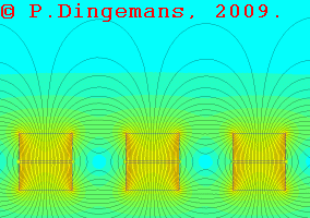
No. Not quite. (EDIT: Looked more closely at your pics, and yes they are close to the same thing)
This is what dual magnets without disks look like. The darker the background, the stronger the flux.
Thanks to Peter Dingesman
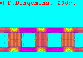
Using the same dual magnets, with steel plates, and equivalent color scheme, it looks like this. Purple is strongest, light yellow is the weakest
Peter Dingesman again:
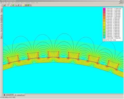
Short magnets will exhibit much worse leakage, as it is easier to "short the magnet from top to bottom", as the distance from the N face to the S face is quite short.
The magnet gap will also dictate how much inter magnet leakage occurs out the front. These pics are for dual axial flux, where you can see how focused the fields are before we move the plats apart. At short air gaps, the thing hardly changes, but as we move out further, small intermagnet gaps look more appealing to the flux, and we "leak" between magnets without traveling out into the air gap we want them to.
These show how the steel focuses the flux lines where it is not dual axial, but single as you have depicted. (Peter Dingesman again)
So with the dual, the max flux is where you predicted, but with a single plate, it is shifted to between the magnets..... not where you originally felt was the right place.
And no, I can take no credit at all for what McGyver has or hasn't done, as he takes not the slightest notice of me anyway.. It is all his hard stubborn work that will get him there eventually. He's keener than mustard..... but a born maverick I think.
Go Mac, I watch with interest (and less hair than before)
and I'm not that bright either.
............oztules
Edited by oztules 2010-07-14Village idiot...or... just another hack out of his depth
Oztules, Thanks for the picture show. It really helped me get a better grasp on this part of the subject. I think I am beginning to understand the magnetism part. I didn't really understand the flux as a circuit concept, or the peak point of the flux-arch between two magnets. Now it is beginning to make sense to me.
Although my bigger magnets are a paycheck or so away, I will start the planning for the beta version of this experiment. I will wind some different coils for testing and let the group know how it goes.
I do have questions though.
Is there any value in magnet proximity to each other? In other words, should the edges of the magnets touch each other, or are they better separated.
Once it starts producing electricity, how-ever little, what is the best way to get it into a 12 volt battery?
Do you have any opinion of capacitors on the AC side of the rectifier? I know by adding a couple of capacitors after the rectifier the ripples in the DC can be smoothed into cleaner DC, but I am not sure what value capacitors would have pre-rectifier.
Thanks again!!!
"As for me, all I know is that I know nothing." - Socrates
oztules Guru Joined: 26/07/2007 Location: AustraliaPosts: 1686
Posted: 02:44pm 15 Jul 2010
Copy link to clipboard
Print this post
Magnet proximity:
This is fairly flexible, and is really a function of how desperate you wish to throw money at the project, and your air gap.
General rule 1 is about 1/2 a magnet width between magnets.... (unless of course general rule 2 ....at least the air gap width...suits us better )
Now like all general rules, they are there to be broken, and in this case it is true as well. If you need to get more power into a given design, then more magnets will do it, even if used poorly (from a purists view perhaps), so you can squeeze them up a bit and still get better results... despite massive leakage.
In essence, for reasonable performance from a GIVEN set of magnets, then it is the air gap that will dictate the closest inter magnet spacing.
The only reason we have to space the magnets apart is to stop them leaking flux to each other, rather than crossing the air gap and passing through the coils..... so it stands to reason, that if the air gap is such that the majority of the flux crosses it, rather than leaking next door..... then we are on a winer.
So the second rule of thumb, is ignore first rule, and instead, if the inter magnet space (side by side) is the same or more than the plate to plate magnet airgap, then leakage will be very minimal. This turns out in most instances to be closer than the 1/2 magnet width in the case of round magnets, and not so with rectangular ones.....hence the general rule stated in the first place..... it is reasonable in most cases.
Eg, for round magnets 2" x 1/2 inch thick, best air gap will be about 3/4", and so magnet side by side can be as close as 3/4" for low leakage. Here 1/2 a magnet width would have been 1", so we can close it up a bit more than the general rule would have us believe IF we need to..... but winding window is better if left at 1" at least....
For the other popular size, 2" X 1" X 1/2" rectangular ones, the air gap will still be about 3/4", but this time the most compact size will be 1/2 magnet width.. which is 1/2".... at the closest point. (inner radius). Leakage will be a little higher, than 3/4", but will perform well. (3/4" probably a bit better... and more winding window as well)
I said it was flexible, and luckily so. If we want maximum power, we can space the magnets further apart on a slightly larger disk to get bigger winding spaces, for more copper... more current, if were light on magnet, we may do this just to get more copper in there to lower our losses on the greater number of turns we will need with less flux... it's all just a compromise between what you want and what is available to you to try and achieve it.
But no, we definitely don't want them touching.
[quote]Once it starts producing electricity, how-ever little, what is the best way to get it into a 12 volt battery?[/quote]
Best way is to rectify it and put it through the mythical Maximum Power Point Tracker (MPPT) and on into the battery.
Normal way is to rectify it and connect it straight to the battery.
Other ways exist, such as capacitive coupling, boost converters, buck converters, series resistance (to combat stall) etc.
Simplest way is to wind your coils correctly.... rectify it, and direct drive the battery as tradition would have it...... simple is good.
[quote]Do you have any opinion of capacitors on the AC side of the rectifier? I know by adding a couple of capacitors after the rectifier the ripples in the DC can be smoothed into cleaner DC, but I am not sure what value capacitors would have pre-rectifier[/quote]
We don't use caps on the AC side for filtering. Gordon has started a thread of monumental proportions where we discuss this.... I shudder just thinking about it.
We can use caps on the AC side for load matching of the prop to the load. This encompasses power factor arguments, changing the current point where the synchronous impedance (mostly armature reactance) takes control of iron cored machines, and changing the effective impedance of the load seen by the prop.... for an AXFX, I would not entertain these as vital in any way... for an F&P, there are merits in using Caps on the AC side of things.
Caps after/or involved in the rectifier, are only useful in their ability to act as quasi boost converters. This should only be undertaken if your windings are deliberately undercooked.
Here you wind for very late cut in, and voltage double to fill the gap between where normal cut in would have occurred, and where true cut in is occurring..... affectionately known here as cap doublers. (probably best to wind properly for your local conditions, and dispense with this complication, and use the airgap to tune it)
The batteries smooth the current out sufficiently for flat voltage to the DC loads. Caps will make no noticeable difference here, and the batteries could care less.
The batteries also act as the voltage regulator until float voltage is approached, then a diversion load is required to prevent over charging. (once gassing starts, the voltage can rise out of hand, and annoy your inverter unnecessarily)
..............oztulesEdited by oztules 2010-07-17Village idiot...or... just another hack out of his depth
You have given me a lot to think about. I will study it over the next couple of weeks.
I think my new rotor will be a bit wider, 7 inches as apposed to 5.5 inches. That should give me a 1/2 inch gap between my 1 inch neos. It will also give me more room for coil changes. (ie. thicker wire, or multiple strands per coil.)
[quote]
Simplest way is to wind your coils correctly.... rectify it, and direct drive the battery as tradition would have it...... simple is good.[/quote]
OK, simple is what I understand now, I will stick with simple until I understand more of what I am doing.
One question I would like to start with deals with load seen by the prop..
[quote]We can use caps on the AC side for....changing the effective impedance of the load seen by the prop.... [/quote]
How can one use caps to change the effective impedance of the load seen by the prop?
Thanks Again!!"As for me, all I know is that I know nothing." - Socrates
oztules Guru Joined: 26/07/2007 Location: AustraliaPosts: 1686
Posted: 10:41pm 16 Jul 2010
Copy link to clipboard
Print this post
Anything you do down stream of the prop, will affect it's load, and so performance.
If it is overloaded, (stiff load), it's TSR will drop, and prop efficiency will suffer. If we have an over wound alternator (voltages rises too quick for the TSR ), we can use resistance to lower the load, and let the prop get going. We can use series Capacitors to do the same kind of thing also.
In this instance, it may be better than just a resistor, as it will be frequency dependent. So at low rpm, it will present as a low load to the prop, and it can get out of stall territory.
As the rpm increases, the capacitor will be less of an impedance to the AC, and more current will flow..... a variable resistor if you will.... It comes with it's own problems.
The prop is effectively a transducer between the air and the alternator. It deals with the problems of gripping the air and turning that into rpm with a torque component.
It's impedance to the air (mechanical impedance) is modified by the alternator's torque requirements...
These in turn are reliant on the electrical impedances within it and external impedances in series with it ... input side or output side ...(caps can effect these parts)......an engineers nightmare.
..........oztules
It is best to wind sensibly for your given wind regime, and direct couple.
Village idiot...or... just another hack out of his depth


 )
)
 zutules, Thank you for getting back to me!

