Notice. New forum software under development. It's going to miss a few functions and look a bit ugly for a while, but I'm working on it full time now as the old forum was too unstable. Couple days, all good. If you notice any issues, please contact me.
kitestrings Senior Member Joined: 23/04/2014 Location: United StatesPosts: 102
Posted: 07:59pm 27 Nov 2017
Copy link to clipboard
Print this post
One more update -
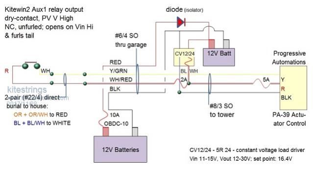
I did a bit of rewiring over the holiday break. Basically I changed the circuit so that the load driver is boosting both the actuator and the control circuit back to the Classic charge controller. The control wires are some ~400' away, and we're using just a double pair of phone wires for the UG section to the house. This works much, much better now:
flc1 Senior Member Joined: 20/11/2011 Location: New ZealandPosts: 242
Posted: 09:15pm 27 Nov 2017
Copy link to clipboard
Print this post
Thats good KS , so its all sorted now? operates how you want it?
kitestrings Senior Member Joined: 23/04/2014 Location: United StatesPosts: 102
Posted: 02:30pm 28 Nov 2017
Copy link to clipboard
Print this post
Yes. In hind-site I should have gone this route. Sometimes it takes me a few tries to get things right ;>]. I found that the signal wire had just enough voltage drop that it was affecting its reliable operation. Also, in cold weather the actuator motor needs a “stiff” somewhat elevated voltage to get it moving. Last night got down to about 5 degF (-15 C) and it worked fine. It’s rated to -15C, but I suspect the white lithium lube is a bit thicker at the lower end of spectrum.
The schematic appears busy, but the concept is not. We have a small, existing 12V battery bank that runs the OH doors and a few lights in the garage. It is tied to our old, tried-and-true Trace inverter. I wanted to avoid having a battery or power supply outside at the tower, due to all the weather/temperature considerations. So, we added a single 12V battery in parallel with the Trace bank, just inside the shop closest to the tower. This battery is isolated from any load(s) by the diode, but it can be charged from the existing sources – primarily the little Rutland charger, and periodically from a trickle charger.
The control wire is long, but is really just an “ignition” signal to the actuator control operating through a dry-contact relay. With the “auto-return” function enabled and 12V+ present, the actuator travels to preset 2 (out, unfurled); with the 12V+ removed, it travels to preset 1 (in, furled). We’ve had some terrific winds lately. Sunday I started the turbine after breakfast and we logged just under 6 kWh by the time the wind died out around 7-8 PM. The PV array was .3 kWh for the day. We can live with this performance.
flc1 Senior Member Joined: 20/11/2011 Location: New ZealandPosts: 242
Posted: 01:04am 29 Nov 2017
Copy link to clipboard
Print this post
thats good output for the day, can see your turbine is making a good contribution towards your electricity needs.