
|
|
Forum Index : Windmills : Lucas Generator A900R L3
| Author | Message | ||||
| salvington Newbie Joined: 04/02/2018 Location: United KingdomPosts: 6 |
Being a new member please forgive me if I am in on the wrong forum. I am a volunteer at the High Salvington Windmill in Worthing Sussex UK. The main windmill was originally built around 1760 & was used up until about 1900. It fell into disrepair & was restored into working condition with much effort & expense about 30 years ago. Since then we have added another three small wind powered devices. Two pumps & we are presently trying to get a Freelight generator operational. Enough of background. The Freelight unit was found in a field fitted on top of a wind pump tower. The wind pump was non operational. Our problem is the generator unit. It would be great if someone could provide any expanded drawings of the unit (appreciate it may be a holt grail). We have had the unit rewound & it generates but there is a field fuse one end of which appears was attached to an external post with (possibly) a spring steel (guess!) running between the external post & the brass fuse carrier. Seems to be a similar arrangement internally. Information on the reason for this would be appreciated as the brass fuse holder is screwed into the generator end plate & would give a perfectly adequate earth path for the fuse. Present plan is to replace this connection but want to fully understand the unit. Numbers on the caseing as follows: 24V >>>------------>451 24522A Type: A900R L3 Unit is 6 inches in diameter & is made by Joseph Lucas (better known in the classic motorcycle fraternity as 'The Prince of Darkness' FYI|: We have refurbish the tower (metal not wood - this as found), the wooden propeller. Fitted a battery box & are trying to arrange a voltage regulator together with load lights. The regulator etc are proving problematic. |
||||
disco4now Guru Joined: 18/12/2014 Location: AustraliaPosts: 1133 |
Hi, Sorry I can't help, but thought I would post a picture of one I saw on my last trip into South Australia. It is in a shed/museum in the abandoned town of Beltana in outback South Australia. 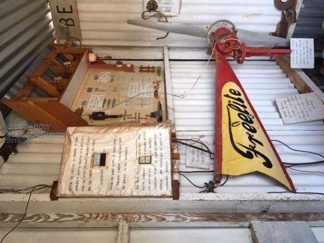 Hope someone can help. Regards Gerry F4 H7FotSF4xGT |
||||
Madness Guru Joined: 08/10/2011 Location: AustraliaPosts: 2498 |
I am not familiar with them but Lucas is a very common generator for cars from that era, it would be worthwhile taking it to an old school auto electrician. There are only 10 types of people in the world: those who understand binary, and those who don't. |
||||
| Boppa Guru Joined: 08/11/2016 Location: AustraliaPosts: 816 |
Any pics? I havent been able to find any hits for that part number, at first I thought it might be a c45 series, but I am now thinking that that 451 is the date stamp (ie april 1951) pics might give more clues as to the type as the part numbers I havent found in any lucas literature to date (style of brush holders, end cap designs, pole piece mounting and shape etc are often a clue as to the base unit, which was often modified for specific end users eg they often used a common core with different end caps and even extra connections etc for specific users- a common core was used for both humbers and jensens, but with different mounts on the end caps Its been years since I have even seen an old lucas generator I second the suggestion of finding a local retired autoelec (most newer guys arent likely to have even seen a genny in person, retired ones more likely so) There are many possibilities of what/how it works- some used self excitation methods that cut in once the wind speed/genny revs got high enough, others had a centrifugal switch arrangement to connect the fields to the battery once a certain windspeed was achieved They needed some form of control system, as the field windings would rapidly discharge the battery if left connected without any wind generating power Finding the correct reg if you dont have one could be problematic, as many regulators are model specific to their generators edit to add typical, just posted and then found at least a little about them... looks like my theory on the dating was wrong- or yours is a lot later than this one Lucas A900R Dynamotor about 1/2 way down the page has some info on how it works by a guy who has one on his 1932 Morris Cowley.... you may be able to track him down and contact him for more info?- try his homepage? |
||||
| Pete Locke Senior Member Joined: 26/06/2013 Location: New ZealandPosts: 184 |
....At that age, they probably use a carbon pile regulator. This is OLD school regulation of the time. If you Google 'carbon pile regulator' you may find a back link to your generator. It was a mechanical heat adjusted system that bought a series of fingers onto a, well, stack of carbon washers. Only the Pom's could come up with a system like that  . . |
||||
| Boppa Guru Joined: 08/11/2016 Location: AustraliaPosts: 816 |
Its a weird beast, its both a starter motor AND an generator in the one unit... Dont know about later models but the wiring diagram I found is a weird setup- its a constant voltage, constant current output apparently- with an internal field resistor inside, and an external one- usually fitted to the headlight switch(probably the one on the outside of his case) that basically increases the current output when the headlights were turned on.... ????? I didnt find it at first as I was searching for generators, and lucas list this as a dynomotor, apparently bosche and several other companies made versions of it- and more surprisingly they are still used in some volvo marine motors as well (suppose its cheaper than a seperate magneto charging circuit if you are going to put in a starter moor, might as well use it for charging too if its only light loads light running lights and the like for small boats Why it was being used in a windgenny???- anyones guess- ex manufacturers stock they could get cheap maybe? |
||||
| salvington Newbie Joined: 04/02/2018 Location: United KingdomPosts: 6 |
First - thanks to all for replying. It's all grist to the mill . I have taken some photos & added them to 'Google Photos, so hope that they will be clear enough. A) The attached plate (photo 3) has the following written - dougt that it will help much! Joseph Lucas Ltd Dynamo must be mounted with this label on top. Birmingham England. B) Images 1&2 show a general view of the dynamo (1) & (20 shows the casing stampings. C) Images 4,5&6. (4) is a top plate view. (5) shows the post (mentioned in original post). It is top the right of the brass fuse holder. (6) shows the fuse holder internal connection using a spring plate which is then attached to the field windings. D) Images 7&8 show the brush holders, springs etc. E) Are capacitors to prevent radio interference. https://photos.google.com/share/AF1QipOX0ZvLrkPaaAKihDEPdZQ78zzBa3XDba5DgTYSO9B0a3NGUw5uR2oGOdH_7uQ7Dg?key=SllzeXhUSnQxW TYwa1dSRHlPODBiSUhURk12bDVR |
||||
| Madness Guru Joined: 08/10/2011 Location: AustraliaPosts: 2498 |
Your photo link just gives this "404. That�s an error. The requested URL was not found on this server. That�s all we know." There are only 10 types of people in the world: those who understand binary, and those who don't. |
||||
| Boppa Guru Joined: 08/11/2016 Location: AustraliaPosts: 816 |
When you copy/paste it, there is an extra space added to it about 2/3 of the way along where the wraparound to the new line is link |
||||
| salvington Newbie Joined: 04/02/2018 Location: United KingdomPosts: 6 |
Apologies for the photo link not working I'll try this one. https://photos.app.goo.gl/u4Cz4dRnbRLk2ena2 It worked for my wife!! |
||||
| Madness Guru Joined: 08/10/2011 Location: AustraliaPosts: 2498 |
I think your best bet is my earlier suggestion of an old school auto electrician. There would someone out there that worked with Lucas generators every day at work and would know them like the back of their hand. There are only 10 types of people in the world: those who understand binary, and those who don't. |
||||
| Boppa Guru Joined: 08/11/2016 Location: AustraliaPosts: 816 |
Not many would have come across these before Madness, the A900R is a strange beast indeed- its not a standard dynamo aka generator, its both a starter motor and an generator in the one unit. They had a combination field winding, part of which is dual duty for both functions. It apparently doesnt use a regulator in its standard configuration, with basically only two output levels- low and high amps out, set by changing resistance in the field windings. Add in the three brush system they normally had, and many auto sparkies (even the old schoolers) would be struggling to figure out how it works, I'm still not exactly sure myself as there is very little literature about them around (and I been in the field for thirty years, did some of my apprenticeship playing with gennies, but they were pretty rare even back then lol) Add on this has probably been modified for use as a wind genny to boot and i's a big ask, any autoelec could probably nut it out eventually, they arent that complicated, but as a paying job would be $$$ If they know its history as a combination dynamo/startermotor (hence the dynamotor tag) it would be a lot quicker to decipher its workings- for many that didnt know its original use would spend a lot of time trying to figure out what and why they had the extra heavier windings in there etc, add in no original regulator (that may have been modified in its new role as a wind genny) and you have a real cludge of a beast lol (for those that missed it before, corrected link for photos is available here Pics ) eta do you have pics of the steel 'springs'- I suspect what you are looking at those two 'springs' are actually a wire wound resister, these are the original 'regulator' that gave you the 'high amps out' or 'low amps out' settings... |
||||
| Boppa Guru Joined: 08/11/2016 Location: AustraliaPosts: 816 |
I dont know how much they modified it to become a wind genny (I suspect that it was supposed to charge a 12v battery, despite being marked as a 24v unit, as it would start charging much quicker into a 12v battery ie lower wind speed, but that is pure guesswork ie what I would do...) remembering that it is pretty much a constant current device. This is for an earlier model, but I suspect they didnt change it that much, at least should give a starting point 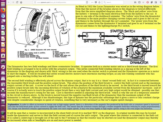 |
||||
| salvington Newbie Joined: 04/02/2018 Location: United KingdomPosts: 6 |
Boppa at the below link are a few photos of the springs - not sure that they are any clearer that previous ones. Must say I have never come across or been aware that these were used as a resistor. Think that you may have a point re the use for charging a 12V battery(s). It will produce over 30V attached to an electric drill but I very much doubt that the propeller would ever get to that speed or have the power to turn it at that output. https://photos.app.goo.gl/x65p1lWrvdECK9VE2 Madness, we have been trying to find an 'Old Timer' but unfortunately been unable to find anyone, that combine with the fact that I reckon that we are probably the 'Old Timers' now!! One of the other volunteers has come across another mill enthusiast who thinks that he may be able to do something - here's hoping. Whatever I will let you all know how things go. |
||||
| Madness Guru Joined: 08/10/2011 Location: AustraliaPosts: 2498 |
Do you have any vintage car clubs near you? They will know someone who is experienced in old car generators. There are only 10 types of people in the world: those who understand binary, and those who don't. |
||||
| Boppa Guru Joined: 08/11/2016 Location: AustraliaPosts: 816 |
Ahha, those springs are just the tensioner for the carbon brushes, they do provide some current path but most of the current actually goes through the rectangular brush holder that holds the brush in place ie spring with brush holder on left 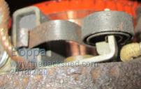 I was thinking of the resisters that they had (usually one internally and one externally) look a bit like a piece of fencing wire in a coiled spring like this 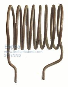 |
||||
| salvington Newbie Joined: 04/02/2018 Location: United KingdomPosts: 6 |
As you say & what I thought the El flow is via the carbon brush connection wire. Springs giving tension onto the carbon so that good contact with the commutator is maintained. Haven't noticed any coil as you show. |
||||
| Boppa Guru Joined: 08/11/2016 Location: AustraliaPosts: 816 |
When used as a dynamotor there was originally one inside that connected to the + brush and went to one of the field windings, and another on the outside that went from the F connector to the headlight switch- these may have been removed in the conversion to a wind genny, dont know (I doubt the internal one would have been 'accidentally' removed, although the external one is a different matter- it just connected to the + battery connection and could have been disconnected/lost during the years) They may have been removed during the conversion as they reduced the charging output, they may have just ran it flat out at all times, there still has to be some kind of external field reg tho, even if it is just a wind activated switch on the tail as some had, as it would otherwise draw field current from the battery when there was no wind and flatten it Problem is I only have very limited info to draw on for them as a dynamotor, and only 'if I ran the zoo' ideas on what they could have done as a wind genny, they werent the most common beast around in their original role (only a handful of early cars and vans seemed to use them) and altho they 'look' like a generator, internally they are quite different (kinda like a generator and a starter motor all mushed up in the one case, some bits working in both roles, some bits only as a starter, others only as as a genny, add in all the stuff I have found suggests they only had a very primitive regulation system (pretty much low or high current output, at fixed rates). This makes them a strange animal indeed! |
||||
| salvington Newbie Joined: 04/02/2018 Location: United KingdomPosts: 6 |
Hi Gents Been a while but we have finally got the High Salvington fourth wind fan operating. WE are now generating - only to light up a few lights to show visitors how the wind can be used. The solution was designed by a friend of the Mill, an electronic engineer called Barry Flannaghan. He owns & lives above a water mill - Burton Mill. I am posting a circuit drawing, which may be of interest. Please note that the LED type diodes are not necessary - he had a pocket full & used them instead of purchasing. The only LED on view is the first light in the light array, this to show generation even if there is a very light wind. Thanks all for offered advice & help 2019-04-01_192552_Mill_wind_Gen_El_Box.pdf |
||||
| oljunkman Newbie Joined: 20/11/2013 Location: AustraliaPosts: 6 |
Hi guys, as regards the Lucas a900 generator as used on the Hannan's Freelite, I'm not sure what info you require but can tell you what I know. I worked in what used to be the Freelite Dept. at Hannan Bros. up until 1974 when we repaired Lucas starters and generators as exchange units there. There was still heaps of Freelite stuff still lying around and as it was my Grandfather, Les Hannan who developed them, I wanted one as a keepsake. In those days there was only two people left in the place who knew anything about them, one being my father Ray Hannan. I was told that the generator used on the Freelite was an A900 with the field coils rewound at Hannan Bros. There was no voltage regulator, only a standard cutout as used on early motorcycles and cars. Once the generator voltage exceeded battery voltage the cutout would click in and the batteries would charge. The Lucas house lighting batteries were about 70cm tall by 20cm square and were single cell 2v. each. When you purchased a Freelite it came with a small panel which housed an ammeter, fuse, and the cutout which would be mounted close to the batteries. There was nothing to stop the batteries overcharging so you needed to keep an eye on them in case they boiled and the electrolyte level dropped down too far. I used one of those generators as a fast charger on my boat which was a 24v system. The generator was a 32v and I used a diode from a truck instead of the original cutout so it did'nt matter whether you were charging a 12v or 24v system, as soon as the gen voltage was higher than the batt. voltage, the diode would connect the two. Anyway, I found enough parts to build myself a Freelite which was the last one to come out of Hannan Bros. When the place was sold in 1974 I took home anything that looked like a Freelite part and still have some stuff left. My Dad told me that my Grandfather and his mate Richard "Dicky" Dickson spent years testing the Freelites and the last models, post war, were very reliable and big sellers. |
||||
| The Back Shed's forum code is written, and hosted, in Australia. | © JAQ Software 2026 |
