
|
|
Forum Index : Windmills : F&P windmill help required
| Page 1 of 2 |
|||||
| Author | Message | ||||
brett Newbie Joined: 08/02/2006 Location: AustraliaPosts: 39 |
Hello everyone. This might be a-bit long I am sorry. The Back story I am not new to renewable energy. I have experience with solar systems to capture energy for several projects. Firstly I have small solar panels and battery setups for my work to power equipment to remotely monitor air, soil and water. Secondly my brother in law has a remote 12v setup in a lifestyle block not far from Goulburn NSW that I have had experience with. Finally my father in law owns a beautiful bush block near Jenolon Caves NSW which I have helped set up, including a solar system. 3 Weeks ago my father finds out that you can use F&P motor to generate electricity. As an electrician and washing machine repairer he has 3 of these motors that owe him no money that we can use. Using good old google I set out to find out how to do it. With special thanks to Glen Littleford and his wonderful website I have built a version of his F&P wind mill from scrap bits and pieces. Glen�s website also directed me to Hugh Piggott�s website. From Hugh�s site I was able to build a set of blades to suit my mill. I will endeavour to get the photos of my progress up on the net for all to see as soon as possible. The situation I am at now is that I need some advice to move forward on a few aspects of this project. 1: I have not been able to determine what size and weight the tail should be. Also how to I set it to furl at the correct wind speed (what ever that speed is?) 2: I plan to rewire the stator in 2 pole star configuration as per Glen�s website. Is this the best option? 3: I need advice on a simple and easy 3 phase rectify. I am good with wood and metal but no so good at small electronics. Is there a off the shelf item, or easy solutions. 4: I need advice on a regulator and a set up for a dummy load, which is very simple and easy, maybe off the shelf. Things you might need to know. The current system that this mill will be wired into has the following details. The set up is 24 Volt, currently has 2 40w 12v solar panels, a medium sized battery bank and small inverter. It is powering a cabin small in size and is used for lights, and small appliances. Soon we will be upgrading the inverter to include larger appliances and a fridge. We use the cabin up to twice a month for usually 3 days at a time but do have much longer stays (1 week or more) periodically. Thanks in advance for any help Brett |
||||
solarmike Newbie Joined: 14/11/2005 Location: CanadaPosts: 26 |
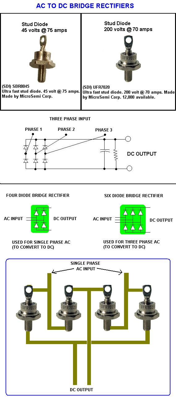
hi Brett, I am wondering why you are planning to wire your stator for two poles? I enjoy poly-phase alternators and can help you make the proper connections to rectify them. I can also help with dump load circuits. But first I drew up a diagram showing how to hook diodes up to form a rectifier. I recommend using diodes like the ones shown. You can easily take some aluminium bars and drill and tap them so that you can screw the diodes into it. The aluminium acts like a heatsink and also allows you to add more wire connections up to it. Be sure to keep the diodes on separate pieces of aluminium because the exterior metal casing of the diodes are conductive. A high current homemade bridge made with the diodes shown will take tons of abuse and last a long time. It is also cheaper and self satisfying. You can find these diodes at: http://www.surplussales.com/semiconductors/diodes-3.html I am solarmike |
||||
| dwyer Guru Joined: 19/09/2005 Location: AustraliaPosts: 575 |
hi Solarmike As you show some excellenct drawing of the diodes which is good and help other to understand the system and also very much simpler many metal workshop use Mig welding ,plamsa cutter all use diode setup as you shown and many diode can be brought from welding repair shop as sparepart or find one at scrapmetal yards as some of mig welder thrown out for newer model ian |
||||
| Gizmo Admin Group Joined: 05/06/2004 Location: AustraliaPosts: 5187 |
Hi Brett The tail on my windmill is about 1 meter long, and has a tail fin made from 3mm aluminium plate. I built the tail using my very technical "gut feeling it should work ok" design techique. It furls in stong winds, just as the blades are starting to stall, so I must have it pretty spot on. There would be a way to calculate the pivot angle, tail length, fin area and weight, but it is beyond my understanding. Maybe someone else here would have a better understanding of the maths. But I prefer to build things and then fine tune them to get the best results. If you feel your windmill is furling too early, add some weight to the tail, or move the tail fin further out. If the wind is howling and the windmill is spinning so fast it scares you, then you need to make it furl earlier by moving the tail fin closer to the pivot. I would never consider building a windmill without a furling tail. The furled tail is so simple and yet works so well. I've seen my windmill suffer several storms, bucking around in the wind and almost fully furled. The only reason it survives the storm is because it did furl. Glenn The best time to plant a tree was twenty years ago, the second best time is right now. JAQ |
||||
| brett Newbie Joined: 08/02/2006 Location: AustraliaPosts: 39 |
Thanks for the information people. PLan to finish the tail and paint it next week, will gather some information about the required electronics and talk to my dad and step dad who both have some electronics experience. Solar mike. Those diodes look great I just need to find them in Australia. I am having trouble with my web server, but I have managed to get 1 photo from 4 to work. Try this link to see the progross so far on the generator. http://www.members.optusnet.com.au/~taara/Windgenmotor2.JPG Brett |
||||
| Gizmo Admin Group Joined: 05/06/2004 Location: AustraliaPosts: 5187 |
Hi Brett You know, that is the first picture I have ever seen of one of my designs built by someone else! Close up anyway. Glad to see someone understood my plans. Glenn The best time to plant a tree was twenty years ago, the second best time is right now. JAQ |
||||
| brett Newbie Joined: 08/02/2006 Location: AustraliaPosts: 39 |
The plans were very easy to follow, thank you very much. I have just been trawling through the old posts and found a post of yours that shows pictures of different wiring methods. I think I will use the star 7 pole, to rewire the F&P. This is described as a good allrounder and the most common. Which suits me. I am located at Blayney NSW and have line of sight to a comercial wind farm, but dont need maxium performance. Do you think this would be suitable. Brett |
||||
| brett Newbie Joined: 08/02/2006 Location: AustraliaPosts: 39 |
I a mplanning to use a GM car atlernator to rectify the 3 phase. I found at some stage a very good web article on how to pull the alternator apart, which bits to use and how to do it. Does anyone now of such a site. Thanks brett |
||||
Chris Senior Member Joined: 12/09/2005 Location: AustraliaPosts: 146 |
This very site your on, heres a link  http://www.thebackshed.com/windmill/Articles/AlternatorRect. asp http://www.thebackshed.com/windmill/Articles/AlternatorRect. aspAlso for your regulator, if you want something simple. You could get the oatley shunt regulator. Its cheap and easy to build. www.oatleyelectronics.com |
||||
| brett Newbie Joined: 08/02/2006 Location: AustraliaPosts: 39 |
Thanks Chris, I thought it was on this site, but I looked and looked. Must have been boy looks. The Oatley looks the goods but I don't know if it will suit my system and more important if I would be able to do the work. It is such an important part of the system I am temped to buy off the shelf. Brett |
||||
| dwyer Guru Joined: 19/09/2005 Location: AustraliaPosts: 575 |
Hi Brett Well done and picture came out well Anyway to find diodes try BOC or Welding Repair Shop as they do able get some Big Diodes for you might cost you more but is easyway to get it. Something l would like to ask you what kind of welding rod you use to built F&F body? regard Ian |
||||
| Chris Senior Member Joined: 12/09/2005 Location: AustraliaPosts: 146 |
Dude if you want the rectifiers just go to jaycar or dicksmith and buy some 35A rectifiers for 5 bucks. No big deal. |
||||
| brett Newbie Joined: 08/02/2006 Location: AustraliaPosts: 39 |
Dwyer, I had 4 pictures to post but I could only get 1 to work I will work on the others again this week. Thanks for the suggestions, re Diodes, I am still working on that problem, hopefully I will get time this week. As for the welding rods, I tacked it all together with 2mm satin craft rods, then I took the F&P body to work and fully welded with a mig. This week, I plan to make a boss system to attach the blades to the F&P shaft, Add a bracket to mount the rectifer and another to run the cable down the pole. If I get all that done I will do some painting as well. Brett |
||||
| brett Newbie Joined: 08/02/2006 Location: AustraliaPosts: 39 |
I have got the rest of the photos sorted, here are the links. http://www.members.optusnet.com.au/~taara/Windprop1.JPG http://www.members.optusnet.com.au/~taara/Windprop2.JPG http://www.members.optusnet.com.au/~taara/Windprop3.JPG http://www.members.optusnet.com.au/~taara/Windprop4.JPG http://www.members.optusnet.com.au/~taara/Windprop5.JPG http://www.members.optusnet.com.au/~taara/genmotor1.JPG http://www.members.optusnet.com.au/~taara/genmotor2.JPG Brett
|
||||
| peter Newbie Joined: 15/01/2006 Location: AustraliaPosts: 25 |
nice work Brett , i would like some feedback on it's performance as i have not got involved with a fp alternator yet , i have one in my washing machine but the boss won't let me take it out!! Blades look good.. hard to find 1/4 cut douglas fir  |
||||
| brett Newbie Joined: 08/02/2006 Location: AustraliaPosts: 39 |
Peter, Once I get it all together, and up in the air I plan to record its performance and put the results on this board. I have the equipment to measure windspeed and direction, Voltage output, and prop RPM. This will all be logged on a 1 minute time scale and should give valuable information regarding output and how much wind is required to run it. I hope to add watts or amps to the logging process but have not worked out how to do that with my logger yet. This might be 2 weeks away yet. Brett |
||||
| KiwiJohn Guru Joined: 01/12/2005 Location: New ZealandPosts: 691 |
Brett, can I help you with that? If you know the resistance of your load you can easily calculate amps and watts. If you can measure voltage I can tell you how to find the watts.
John |
||||
| brett Newbie Joined: 08/02/2006 Location: AustraliaPosts: 39 |
Thanks KiwiJohn. I hope to get the unit basicly finished this weekend and up next week. Then I will be recording voltage output unloaded to start with and then I will attach a load. From reading into your post, If I know voltage produced and the resistance of the load there is a formula for Watts and or amps. I should be better at this electrical stuff my dad is a sparky. Keep an eye on this post as by mid next week I should have some numbers. |
||||
| brett Newbie Joined: 08/02/2006 Location: AustraliaPosts: 39 |
I have made some further progress over the weekend. Firstly I made a Boss to hold the prop onto the F&P shaft. It is made from Nylon rod and machined in 2 parts. The first is at the back of the prop and is machined to the thickness of the norrow diameter of the spline, then pressed onto the spline to give a perfect fit. The outer piece is machined to the exact outside diameter of the spline and drill and tapped to suit the thread on the shaft. Anyway the pictures may explain things better. http://www.members.optusnet.com.au/~taara/boss1a.JPG http://www.members.optusnet.com.au/~taara/boss5a.JPG http://www.members.optusnet.com.au/~taara/boss6a.JPG Finnaly a picture of where I mounted the bridge rectifiers. http://www.members.optusnet.com.au/~taara/mill2a.JPG This week will be very bust at work so I might not get much done, hopefully I will get the stator mounted and the wiring done, and the tail finished. Brett |
||||
| adam666 Newbie Joined: 01/02/2006 Location: New ZealandPosts: 14 |
Thanks for the great Diode advice Solarmike! just so happens I had a pile of those 45V diodes I was contemplating putting to use, any reason I would use bridge rectifiers over these? or not? got a few of those lying round too. Brett: Nice hub! How strong is that nylon though? is the nylon actually forced onto the spline? I was thinking along the lines of all steel contruction for strenght. But after getting a quote to get a steel female spline made up Im looking for other options. Cheers Adam "to capitalize on windy wgtn" -excuse the pun :p |
||||
| Page 1 of 2 |
|||||
| The Back Shed's forum code is written, and hosted, in Australia. | © JAQ Software 2026 |

 It's looking good so far. Keep us posted.