| |
Page 1 of 3   |
| Author |
Message |
imsmooth

Senior Member

Joined: 07/02/2008
Location: United StatesPosts: 214 |
| Posted: 12:48am 27 May 2008 |
 Copy link to clipboard Copy link to clipboard |
 Print this post |
|
Does delta configurations give that much better power than star at high rpms that it is worth having a switch to convert from one configuration to the other? Can anyone give a quick reason why Delta gives more power than Star for a fixed rpm? |
| |
Gill

Senior Member
Joined: 11/11/2006
Location: AustraliaPosts: 669 |
| Posted: 03:05am 27 May 2008 |
Copy link to clipboard |
Print this post |
|
Certainly,
In Y between each phase is 2 coils in series whereas in D there is only 1. Because a coil will produce a set voltage at your set rpm, Y with it's 2 in series will add to produce higher voltage than just the 1 of D.
Ohm's Law: Power equals Volts X Amps (any rpm)
With an input power the same for Y and D,
for Y the voltage(twice D) means 1/2 the current,
and for D voltage(half of Y) means 2 x current.
and Current charges batteries once the input voltage is higher.
Rough but Quickly Explained. 
was working fine... til the smoke got out.
Cheers Gill _Cairns, FNQ |
| |
oztules

Guru

Joined: 26/07/2007
Location: AustraliaPosts: 1686 |
| Posted: 02:20pm 29 May 2008 |
Copy link to clipboard |
Print this post |
|
Hmmm,
What is not obvious at first glance is that for star, the current must go through two coils, so effective resistance is double the resistance of a single coil set, but the voltage is only about 1.73 times the single coil sets voltage because of the vector addition of the two out of phase coil sets.
The Delta scenario is even less easily seen at first glance. While we have voltage and current from the single coil set, we also get the vector addition of the other two coil sets adding to get the same voltage as the primary set, and as in star, we get half the current of the single coil set (because it travels through two resistances in the other two coil sets). This gives us 1.5 times the current of the single coil set.
So Star gets us 1.73 times the voltage of the delta setup, but has 3 times the effective resistance of the Delta configuration.
Power equations: W=ExI and I=E/R so W=E^2/R.
So for an example:
For a single coil set, that reaches 1v at X test rpm with 1ohm for the coil set, we get this:
Star will develop 1.73v. The resistance will be 2ohms (two coil sets in series) so power will be (1.73v x 1.73v)/2ohms = 1.499 watts
For Delta it will develop the 1v for the original coil set ... but resistance will be .667 of the original coil set ie .667ohms. So (1v x 1v)/.667ohms = 1.499 watts for Delta as well.
So Power will be the same regardless of configuration.... so why is delta better at higher rpm??
If we look at the impedance of the power source, we see that the star configuration is 3 times the impedance of the delta configuration. If both systems drove loads equal to their own impedance, there would be no difference in output in both systems (disregarding circulating current losses in a poorly designed delta).
It is because we are driving a fixed low impedance load (batteries) that the difference between the two systems diverges a great deal when the power starts to get going.
The batteries present a low impedance to the alternator, and so impedance matching is better performed by delta, but delta's cutin is 1.7 times higher than star. So to charge at a lower cutin, we need star, and at lower power, the losses are manageable to the stator (regards heating) but as the revs increase, the power increases, and will disapate in the higher impedances more easily than the lower impedance battery... so the stator heats up, resistance of the wire goes up, and we set the stage for thermal runaway.... we must furl, OR switch to delta. The better impedance match between Delta and the batteries means more of the produced power goes into charging rather than heating up the stator. As the resistance is 1/3 star, our gains are worthwhile.
It's not all one way traffic though. If we chart the unloaded voltage against the rpm for the two systems, we can subtract the batt voltage from the open voltage. From this we get the "forcing voltage". The forcing voltage squared / the resistance will give us the power for each system.
As we increase rpm, at some particular rpm, the two curves will cross each other and it is from this rpm onwards that delta will be better. Below this point, star will develop the maximum power for the system. (deliberatly not taking into account the diode voltage drop, and the 1.414 ac/dc conversion here to keep it simple)
Hope that helps some
.........oztules
Village idiot...or... just another hack out of his depth |
| |
liqud

Newbie

Joined: 11/08/2009
Location: United StatesPosts: 22 |
| Posted: 06:29pm 12 Aug 2009 |
Copy link to clipboard |
Print this post |
|
great explanation oztules. very in depth. 
Shawn C
Real power is not given its made... |
| |
niall1

Senior Member
Joined: 20/11/2008
Location: IrelandPosts: 331 |
| Posted: 06:59pm 12 Aug 2009 |
Copy link to clipboard |
Print this post |
|
just a small bit to add...
when i spin up the axial alt by hand you can feel a very slight resistance when its wired in delta...if you spin it up with one connection open and then touch it to make the full delta you can see a slight spark...i,m pretty sure these are the so called parasitic currents delta can allow
probabely only a few watts but enough to make me go back to star (what it was origionaly designed for )....
niall |
| |
oztules
Guru
Joined: 26/07/2007
Location: AustraliaPosts: 1686 |
| Posted: 11:04pm 12 Aug 2009 |
Copy link to clipboard |
Print this post |
|
If you were to wind it perfectly symmetrical, and could guarantee every coil was geometrically identical, then there would be no imbalance, and circulating currents would be all but non-existent.
With bottom of the garden axial design, this is unlikely... however, the F@P gang will have better results as the device is much more geometrically perfect.
With the axial, the very low R of the design, also means that any small voltage imbalance will use up significant power as W=ExE/R.... if R is very small, then this W will increase quickly. In an F@P, the R is high (comparatively) per coil..(include inductive reactance here), and so power lost to circulating current will be very much lower/damped. We lose much more to synchronous impedances in the alt.
The diodes hanging off the end of the alt for battery charging purposes, exacerbate the problem and introduce harmonics from the non-linear diodes, and crest factor /power factor that causes the "sine wave " to be very much distorted. This makes following sine wave rules very difficult... as they become more square as the power increases.... losses losses every where.
...........oztules
Village idiot...or... just another hack out of his depth |
| |
woodchips
Newbie
Joined: 05/01/2009
Location: United KingdomPosts: 27 |
| Posted: 08:19pm 13 Aug 2009 |
Copy link to clipboard |
Print this post |
|
The observation made by Niall1, that you get a spark when completing the connection for delta wiring needs to be written in words 20' high and illuminated.
The spark, and drag when rotated, is caused by circulating currents around the delta windings.
It is obvious, looking at the delta winding wiring diagram that all the coils are joined together, in one great big short circuit. All that stops the whole thing melting is that the voltages induced in each winding are at 120 degrees to each other, AND THAT THEY ARE SINE WAVES!!!!!!!
As soon as harmonics are generated, and they will be due to the non-linearity of the BH curve on the magnetic core, then you WILL get circulating currents. These currents are at the third, ninth and every subsequent multiple of three harmonic.
Note that an ironless alternator will suffer from exactly the same problem. The cause here is not magnetic BH curves, there is no iron, but that the voltage generated is not a sine wave. The voltage induced in any coil has a waveform that is EXACTLY like the magnetic flux density at that particular position. No attempt is made in these ironless alternators to shape the flux, it would be almost impossible in any case. Hence the voltage induced ends up looking like a square-ish wave, with third harmonic levels of possibly 20-30%. This will cause considerable circulating currents.
Symmetrical windings have nothing to do with it, it is all down to the induced wave shape.
To put some figures on it. If the alternator is generating 30V, third harmonic is 20% and winding resistance is 0.5 ohm then the circulating current will be 30x0.2/0.5 = 12A. And that is just one phase.
The summary is, NEVER use delta connection in a wind generator alternator.
I reckon this must be the single greatest loss in a windmill alternator.
Bob
|
| |
carl1
Regular Member

Joined: 16/04/2007
Location: AustraliaPosts: 79 |
| Posted: 10:18pm 13 Aug 2009 |
Copy link to clipboard |
Print this post |
|
Hi Bob
Would it increase the output by rectifying each phase separate in a delta connection?
I have measured input and output recently on a F&P 60DS and an F&P 80SP into 12volt batteries.
Efficiency, power input,rpm & torque versus charging 13 Volt & amps came up between 61 and 69%
Harald |
| |
GWatPE
Senior Member
Joined: 01/09/2006
Location: AustraliaPosts: 2127 |
| Posted: 11:53pm 13 Aug 2009 |
Copy link to clipboard |
Print this post |
|
on my 4phase AxFx mill alternator I use independent rectification of each phase, and these are wired in parallel. The configuration with very rounded output waveforms only produced output this way. The price I had to pay for max use of magnets and wire available.
The only drawback would be polarised wiring with indep rect.
My new design is designed for 3phase star to reduce the long term corrosion issues of transmitting DC in a damp salty environment.
Gordon.
become more energy aware |
| |
oztules
Guru
Joined: 26/07/2007
Location: AustraliaPosts: 1686 |
| Posted: 01:41pm 14 Aug 2009 |
Copy link to clipboard |
Print this post |
|
I'm sorry Bob, but we appear to differ again.
Begin long tedious ..... whatever..
It is obvious that you have the theory well in hand, for classical alternators, but the practical asect of axials is just not there.
With the dual axial a lot of effort is used to shape the field, involving large quantities of heavy steel to provide return paths for the flux...in fact it can be empirically measured when coil testing, just how much difference air gap spacing can effect the field concentration. With a twin disk axial, there is no discernible change in EMF regardless of the distance one places the coil from the magnet face.
This indicates a field of relatively even intensity from one magnet to the other, of uniform strength, and matching the magnets shape. Testing with a single disk, shows the complete opposite, and that the induced EMF in the coils is very much dependent on the distance from the magnet face. This means in a thick coil, all sorts of things are happening.... but it is the coils shape in both instances that dictate the waveform. If we wind the coil to suit, it seems to come out very close to perfect.
I used round coils with round magnets. By changing the coil's hole diameter, I could induce the square shapes or peaky shapes or as perfect a sine as I could tell. If the hole size reasonably matches the magnet width, it seems to be a so close to perfect sine wave as to not matter. It IS the coil geometry that dictates the wave shape. The field shape is a given for the design, from there it is simple coil manipulation which changes the wave from square to peaked.
The comment was brought about by Nials observation. It is not mine. I can hook my axial up as star or delta on the test bench, and spin it by hand and it spins down very slowly in either combination, star or delta. It generates voltages in excess of 50v with a hand spin, and has a R of somewhere near .7R..(published here somewhere I have forgotten exactly now). and in delta is only about .23 or thereabouts. There is no discernible drag which in your numbers is "To put some figures on it. If the alternator is generating 30V, third harmonic is 20% and winding resistance is 0.5 ohm then the circulating current will be 30x0.2/0.5 = 12A. And that is just one phase." I think I would notice 50x.2/.23=43A...for just one phase....it would spin like a brick. This just does not happen in the real world of dual axials.
It IS the coil geometry that will dictate the wave shape. The field is very consistent and well shaped with virtually no leakage... so it is the coils shape and hole size that will determine the wave.... period. If you wish to argue this, then build one and find out yourself. It is not hard. I have done it and seen it as have many others.
If you use rectangular magnets and oval shaped coils,(as Hugh Piggott does) then it gets messy, and it is much harder to get a true sine wave, and you can wind for square if your keen. Hugh is a strict Star person (father of the modern axial flux), so does not bother with waveform..... (he also burns up stators in his larger machines like the Nirvana, so Delta loses are not at fault..... but high R star is.) I suspect Nialls is of the Hugh design with rectangle magnets and oval coils.
The hand placed coils in the axial are prone to be improperly centred and aligned as well. It is not an exact business. As a consequence. non-symmetry is almost a given unless your very careful. If non-symmetrical, then the phase angles are incorrect, and roughly 120 degrees is about what we get... you can guess the rest..... for an axial it is symmetry and geometry that dictates the wave shape and phase angle. We are stuck with the field shape and have to work within it's constraints. Another problem with rectangular magnets, is that most have to wind the coils ovoid, or triangular(ish) to fit the inside of the coils into the diameter as it diminishes towards the center, and this means the geometry of the coils does not match the geometry of the field... here you should get wave distortion.... but it does get surprisingly close to sine.. ( not as good as the circular ones though)
Once you start to generate above cut in, the harmonics start. The non-linear qualities of the diodes produce hash on a royal scale.. here is where the harmonics get very noticeable, and Delta starts to become less efficient. As we increase more power, the wave gets flattened by the batteries low internal resistance, and we get crest factor exactly like when we rectify and use big capacitors on the input to offline PWM's.... we get harmonics and square waves aplenty. It is interesting to watch on the scope as this takes hold.... but this is not what Niall was talking about . His was unloaded....
Interestingly, delta wound machines start to really overtake the star versions once star starts to falter from too much R, star works well for slow rpm (higher volts per turn here) and then Delta pours on the power with it's lower resistance windings.... with or without circulating currents.. it will still win in the high power stakes.
This "Note that an ironless alternator will suffer from exactly the same problem. The cause here is not magnetic BH curves, there is no iron, but that the voltage generated is not a sine wave. The voltage induced in any coil has a waveform that is EXACTLY like the magnetic flux density at that particular position. No attempt is made in these ironless alternators to shape the flux, it would be almost impossible in any case. Hence the voltage induced ends up looking like a square-ish wave, with third harmonic levels of possibly 20-30%. This will cause considerable circulating currents."
This is just idle speculation without based on wrong assumptions and is just not supported by my mill or experience I'm sorry. It is easy to manipulate the wave shape to whatever we want, and the whole point of the dual axial is to shape the flux, and put it where we want it. Dinges has done countless FEMM simulations for folks and some for me which have been backed up in practice for those cases he has done for me.(these mostly involving gap distance, and magnet spacing for least leakage etc)
Bottom line. If you get the geometry right, you will be able to replicate a sine wave.
This line is just plain wrong.
"The summary is, NEVER use delta connection in a wind generator alternator."
There are devotees all over the globe that have done motor conversions in particular, who have empirically derived their best winding combinations of their 3 phase motors. A lot of these seem to favour Delta as the best winding for their application and best power output. In other cases, star delta switching is the norm. You are probably approaching it from an engineering problem perspective, and ignoring some of the variables as insignificant, or didn't think of them..... The globe has thousands of defunct windmill projects designed by bright engineers after the oil crisis in the late seventies... and millions of dollars wasted, and dreams of free power dashed. The only thing important to understand is matching the load, and engineers seem to gloss over it and pay it scant regard. Most of those machines never looked like living up to their expectations (poor load matching), and a few were just not strong enough.
Or is it that you think that all the people with star -delta switching schemes are simple, and can't see the resultant differences in real time as they switch between the two systems?? I would think it would be obvious if you were right.... or that the folks running delta are just too dumb to move the wires over to star??
Have a think about it, people do what works best.... and Delta works best for some people in their circumstance... You must match the load... number one rule.
Eg. When one of my blades broke, I simply went from 3 blades to 2 blades.... and from star to delta. why??....yes I know I'm an idiot, but, 2 blades lack the torque to drive the alternator out of stall.... so no power gets generated in star at all (virtually nil anyway), but by switching to delta, the cut in rose to a point where the blades could support the alternator (pulled out of stall), and the mill could once again fully charge my electric car up every day (still not fixed, waiting for the wood to cure a bit more)... and needed a bit of line resistance to soften the alternator (too electrically stiff and had to rematch the load)
So this statement "I reckon this must be the single greatest loss in a windmill alternator." is just demonstrably wrong on so many levels.
Apart from load matching being the first order killer, the second biggest loss is the stator itself if charging batteries. This loss will destroy any stator if the furling fails.... end of story. Strangely, now I think back on it all, I have yet to hear of a Delta wound axial burning out... it is always the star wound types...their higher resistance finally gets them.
If you wonder why, then reconcile a linear wind speed with and squared alternator output to a cubed power input.... driving a static load of very low impedance..... so where do you think the real losses are?.... Remember this, my mill sees 100watts of wind at 5mph, and 18000 watts (yes 18 thousand) of wind at 30 mph. Out of that we just need to match the blades to the wind and the wind to the blades. At 5mph, I won't reach cutin so no power, at 30mph, I will struggle to furl properly, and pump 2kw into the batteries. Delta would do better at the top end, and would likely get 4kw into the batteries if they could take it as R is only 1/3 of star.... by furling, we deliberately mismatch the system and lose some 14kw.... delta loses??? who cares... we need to do what works to match the load. The best match is if we can use star down at low power, and delta in the high power region... and if the wind wasn't so fickle, this would work brilliantly instead of just well.
..........oztules
Village idiot...or... just another hack out of his depth |
| |
niall1
Senior Member
Joined: 20/11/2008
Location: IrelandPosts: 331 |
| Posted: 03:30pm 14 Aug 2009 |
Copy link to clipboard |
Print this post |
|
the alt is one of hughs square mags oval coils...


in my case its definately bottom of the garden mechanics
winding coils is weirdly hypnotic and its easy to get an extra turn or two in there (i.e. the dog barks.. you get an itchy nose etc.)
plus the first ones usually come out a little bit bigger (you get better as you go along) ..its hard to align coils .. i tried printing out cad templets for as much as i could but soldering heavy wires ,enthusiasm etc can move things around a little ... 
as regards hughs design,s theres a danger of not factoring in the human element (like above) as well as the machine......people are tempted to let machines run in occasional storms just to watch the ammeter hit the top..i cant understand that ..a lot of burn outs seem to happen in freak weather
on his last course here watching the way hugh approachs building a machine ,setting up furling , air gap ,possible weaknesess down the road , good pratice etc was an eye opener in itself , never mind the machine ...all this with 16 pairs of hands playing with power tools with gay abandon...
i can only speak for my own take on hughs design ..i provided the personal touchs .....delta accepted
at first i thought i had only nipped the bearings with an extra flat (maybe a bit less) on the castle nut (the resistance like i said was that slight ) only for i noticed the slight spark i,d probabely have ignored it
it had been running in delta a couple of months previously and seemed fine (in hindsight with a slightly different growl) but now i just dont like the idea of a little extra drag (however small) in a machine that has early cut in as one of its main characteristics ..so star it is
i,m curious.... these harmonics , can they make it down the power line to the electronics ?
its all good food for thought ...  Edited by niall1 2009-08-16 Edited by niall1 2009-08-16
niall |
| |
Dinges
Senior Member
Joined: 04/01/2008
Location: AlbaniaPosts: 510 |
| Posted: 09:48pm 14 Aug 2009 |
Copy link to clipboard |
Print this post |
|
+1 on wot da 'tulez dude sed. It's all about matching - whether in electronics, mechanics or relationships.
A 220V/500W halogen lamp matches poorly to a 1.5V AAA battery. A 6V/0.1A toy DC motor matches poorly to the wellpump.
If, by wiring the stator in delta, you gain much more in energy because of better matching than that you lose from circulating currents (taking also into account your particular wind regime), then it's really a no-brainer.
[quote=Niall]winding coils is weirdly hypnotic and its easy to get an extra turn or two in there (i.e. the dog barks.. you get an itchy nose etc.)[/quote]
+1 on dat too. What helps me is counting loudly. And ignoring *anything* that interrupts the process.
[quote=Niall]but now i just dont like the idea of a little extra drag (however small) in a machine that has early cut in as one of its main characteristics ..so star it is[/quote]
About not wanting to lose even a little power.... I strongly suspect the losses in delta are overrated, but never bothered to measure it myself. It shouldn't be too hard to measure circulating current (with a true-RMS meter) of an unloaded generator, wired in delta. If you know the resistance of the phases, I think (someone correct me if I'm wrong) that the power loss would be P=I^2 * 3 * Rphase, where Rphase is the resistance of one phase.
What would be interesting too is to measure the voltage in 'open delta', i.e. in delta except for the final connection to 'close' the loop. Measure the AC voltage. You may well find that it's only 2-3V. Even that makes a spark though.
Your power losses in delta may be less than you fear. In fact, could be so low as not to warrant any consideration. But it's only by measuring we can know for sure. And as Oztules said, it could well happen that a delta circuit better matches the blade and load. If you know how much power you lose in delta, you are more informed in the decision whether it's useful to build a new stator (with fewer windings) wired in star.
measuring=knowing.
[quote=Niall]but now i just dont like the idea of a little extra drag (however small) in a machine that has early cut in as one of its main characteristics ..so star it is[/quote]
You realize that if it cuts in early in delta, it will cut in even earlier when wired in star? By a factor of 1.73, to be exact. If it cuts in at 200RPM in delta, it will cut in at 115 RPM in star.
Peter.Edited by Dinges 2009-08-16 |
| |
oztules
Guru
Joined: 26/07/2007
Location: AustraliaPosts: 1686 |
| Posted: 10:32pm 14 Aug 2009 |
Copy link to clipboard |
Print this post |
|
Niall, ....
Yes the harmonics are a fact of life all through the system.... star , delta, jerryrig, seperate phase rectified (better than delta)... the crest factor and the diode hash make trying to use the wild AC in a digital multimeter (Hz setting) impossible after about 20-30% into the power output... you then need filtering to find the fundamental frequency.
I wouldn't use Delta either as a permanent solution. The losses once cut in occurs don't need to be there... in low wind every bit helps. Rectify each phase seperately and you can loose the small losses. However, once the thing really gets going, the Delta losses are immaterial, large as they may be by then, as you will be going for the furling button anyway. In a good wind, switching in delta can be the difference between burning up your star stator, and developing stacks more power.
........oztules
Village idiot...or... just another hack out of his depth |
| |
niall1
Senior Member
Joined: 20/11/2008
Location: IrelandPosts: 331 |
| Posted: 11:26pm 14 Aug 2009 |
Copy link to clipboard |
Print this post |
|
Peter wrote
You realize that if it cuts in early in delta, it will cut in even earlier when wired in star? By a factor of 1.73, to be exact.
thankyou ....i have a thin grasp of this concept... 
it was just an observation ...something unusual in my machine .. about delta ...i,m kind of sorry now i even mentioned it ... 
but anyway ...Edited by niall1 2009-08-16
niall |
| |
Smart Drives

Senior Member
Joined: 06/07/2009
Location: AustraliaPosts: 115 |
| Posted: 12:03am 15 Aug 2009 |
Copy link to clipboard |
Print this post |
|
Sorry all but as they say actions speak louder than words. I agree with OZTULES . I dont know about other motors but the smart drive motors put out heaps more power after a certain RPM using Delta. Whether they are losing excess power at a point or not it doesn't matter. It is almost impossible to blow one up due to their excellent cooling properties. They have been studied for YEARS !! and with long term RESULTS in hand (not theoretical , which obviously have their place for a specific system) i can say if you want power use Delta. If you want quick start-up use star and if you want both switch from star to delta.
After checking my facts Switching from star to delta is wrong....
The stepper switches from Series to parallel,With a unit wired half and half. or 2 units.
Sorry for any confusion on that point. Delta still puts out more power than star though.
Cameron.
Edited by Smart Drives 2009-08-18
All smart drive parts sold
Custom built turbine parts on
Multicam flatbed CNC Router |
| |
GWatPE
Senior Member
Joined: 01/09/2006
Location: AustraliaPosts: 2127 |
| Posted: 04:23am 15 Aug 2009 |
Copy link to clipboard |
Print this post |
|
All the problems of star/delta go out the window with an alternator wound for power output at the higher rpm. A relatively high cutin, star winding and thick wire. Just use a capacitor voltage doubler/tripler/quadrupler arrangement and no switching system needed. Matching the loading is much easier away from the windmill as well.
Caps in this arrangement have proven to work at the low frequency of a dual AxFx as well. fillm has caps on his AxFx mill now with good results.
Gordon.
become more energy aware |
| |
niall1
Senior Member
Joined: 20/11/2008
Location: IrelandPosts: 331 |
| Posted: 11:03am 15 Aug 2009 |
Copy link to clipboard |
Print this post |
|
the harmonics (noise ?) fact of life is interesting..placing tvs diodes across the fets in the dump controller showed up plenty of spikes (the diodes generally expired after a week or two, the fets didnt seem overly bothered ) i know inductance in the load can be a problem but i often wondered what weird stuff could be coming down the line as well....
the cap matching option seems very appealing....(its a pretty daunting thread though .... .) .)
niall |
| |
woodchips
Newbie
Joined: 05/01/2009
Location: United KingdomPosts: 27 |
| Posted: 02:53pm 15 Aug 2009 |
Copy link to clipboard |
Print this post |
|
Hi Oztules, I think theory is good stuff. At least it is better than your fourth paragraph where the first sentence contradicts the second.
That your alternator would spin as freely when wired in star or delta is a remarkable achievement, but to expect everyone else to manage the same is rather optimistic. I am looking at the design of these alternators from the point of view of people that are inexperienced and new to technology. From simply reading the posts on this forum I would estimate that most people are really struggling with anything to do with electrical design. Even the assumption that someone can make things is probably wide of the mark. Most people have neither the tools or experience in making anything beyond a self assembly set of shelves. But they are still passionately interested in wind power, why not help them to realise a dream.
The enthusiast looks at a windmill and decides to make one. They have never seen enamelled copper wire before, let alone wound a coil. Then there is the neo magnets, and despite every comment and warning the sheer power of attraction these have is stunning. So we end up with some rather chipped magnets, then the coils don't quite look like the photos with wiggly turns and out of round shape. It is this difference to perfection that will demoralise the enthusiast, even though it will work and work well. Here is where the star connection wins, the fact that none of the components are perfect doesn't affect its performance anywhere near as much as delta connection.
Once assembled the enthusiast spins it over by hand. With a sum total of test equipment consisting a DVM how are you going to tell them how to fault find their work? Just what is the result of connecting one coil back to front? Does it matter if some coils are wound clockwise and some counter-clockwise? Just how, exactly, to you tell if one winding of the delta is back to front? Just what, exactly, is the effect of physical misplacement of the magnets?
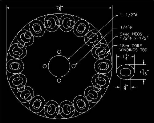
I can go on and on, I am not interested in helping you fault find your alternator, you can manage on your own. I am interested in the beginner, the enthusiast. To that end I am trying to suggest a design inherently robust, and one of the simple ways to do this is to recommend star connection, and even separate rectifiers for each phase. The mechanical is in many ways easier, use 6mm plate here sort of thing, but electricity is a closed book to 99% of the population. I would quite like to reduce that to 98%, and understanding the theory is the only way. Can Nial1 explain why his alternator has 12 coils and 16 magnets? Or fillm uses 12 magnets and 9 coils?Do do this you need to understand what wave shape the induced voltage will be, and what influences this waveform. Likewise there is talk about hash from the rectifiers, explain storage and recovery to the first time user of a rectifier. So rectifying each phase separately gets rid of most of this, but why, exactly?
You say that round coils and round magnets evidently will induce a sine wave, but what is the level of distortion in it? Where are the quantitative values of the harmonic levels, into spectrum analysers now. The statement that the magnetic field "is very consistent and well shaped with virtually no leakage" is nonsense. Just what does the magnetic field look like? Have you tried the small ball bearing on a piece of string test? Thought not. There are magnets next to each other with a N and S pole, most of the flux is going to promptly go between these magnets, not across an air gap that is longer. There is no possible way of insulating magnetic flux like you can electricity with a bit of PVC. The flux lines will take the lowest reluctance (magnetic resistance) path from a N pole to a S pole. So with the iron less alternator, like the photos by fillm, does the coil actually get most of its flux from the flux going sideways between adjacent magnets? What would be the effect of separating the magnets sideways so they are at least the face to face distance, 20mm or so, apart? What if this spacing is increased to 50mm? At least then you can start guessing that the flux really is going through the coils. But, wait, you then have the steel drum, any amount of flux will go to that and back round to the other magnet pole. Does the steel backing plate suffer from magnetic saturation? Probably, so what effect does that have on the flux pattern? So we are now at the point where nothing really is known about the flux paths, hence nothing is known about the induced voltage waveform, all that can be done is poke and hope with an oscilloscope trace as the only measurement, wow. I have never made an iron less alternator, on the to do list but not quite yet. But I will at least design it, build it and measure the results, and if theory and practice don't match then I have to find out why. Without numbers it is just opinion, not fact. Does Cameron have some real numbers to back up the statement made about the F&P generating "heaps more power" in delta than star?
I have had a professional life full of design reviews where the design has been adjusted until it works, any concept of comparing what was designed with what was measured is noticeable by its absence. This has scarred me, hence the 'yes, but?' approach to alternators. What is forgotten here is that almost no one has access to a more knowledgeable person to ask these 'why?' questions. This forum does a marvellous job, but it is still a very poor substitute to a real person. What an oscilloscope shows is immediately grasped, but to operate one isn't quite so simple, and if a gotcha is taken as truth then progress stops.
There have been many different designs of alternator made and used, but just because it is used doesn't mean it can't be improved. All these users around the world must be quite happy with that they have, great. I am trying to pass information and knowledge to those without my background.
I gather niall1 regrets posting his comment, don't. That was the first real description of delta connection circulating currents I have seen, and it is important. All you need now are three current probes for an oscilloscope and you can watch the current flow in real time. A possible alternative, but not so easy to interpret, is to wire in star, connect three equal value resistors, say 1k ohm, to the output wires and other ends together. This will form a star virtual neutral point for the alternator so measuring with a meter or scope from that to the actual neutral point will give an idea of how much the neutral does wander due to imbalance.
Enough, got to leave something for another day.
Bob
|
| |
niall1
Senior Member
Joined: 20/11/2008
Location: IrelandPosts: 331 |
| Posted: 06:30pm 15 Aug 2009 |
Copy link to clipboard |
Print this post |
|
hi Bob
as you mentioned me in your posts i feel i ought to reply
and you are correct i just about qualify as one of your enthusiasts... 
you wrote...
Can Nial1 explain why his alternator has 12 coils and 16 magnets..?
with hughs designs i just copy , thats a given.....it works for me....i have no aptitude or feel the need to analize all his different approaches ..its above my head ...do i need to alter something ?... a tweak here and there perhaps ?..........
erm......on the other hand your loaded question seems to pose a doubt about understanding basic 3 phase principles .... as regards learning something about this i do understand its helpfull to know something (all be it a bit thin.... ..) of the physical relationship of the coils to the mags
..trawling through otherpower for months about 3 phase for me was a start and still is
....an earlier learning curb included a 24 to 18 coil 3 phase (if memory serves)..2 simple single phase alts and one serpentine 3 phase )........basic stuff and yes they were pretty crude..... but then you try to move on a bit and hopefully improve ...the precise wave forms (precise measurement etc..).. arnt so important to me but still of great interest
my point is this
one of the first axial single phase alts was trully awfull ... .. it had 14 mags per rotor , 7 coils that had far to many turns...its own mother couldnt love it...no research.....just unbridled enthusiasm .. it had 14 mags per rotor , 7 coils that had far to many turns...its own mother couldnt love it...no research.....just unbridled enthusiasm
yet when 3 sets of 2 were individually rectified into a 24v batt it could put out bursts of of 300w , yes it was a bruser but i like to think it could have fought its corner against some of the commercial 2 meter 3 phase machines ..
i bought one of these ,it was just a source of embarassment... so i took it down
the 24 mag stator ..3 phase 6 coils per phase (its been a while since i looked at it )..doubtless the wave forms were interesting i have no idea...... but you got a lot of copper in there for your buck.. ..
the magnets were small though 48 in total and slightly the wrong size...all i could afford at the time ..a learning curb nonetheless
the theory is interesting ...but charging a battery was the ultimate goal ...the end justified the means if you like... apologys to all (especially peter) for the rant ...
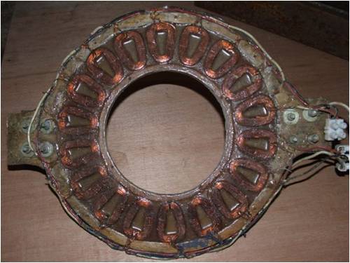
ps ..a better pic from fieldlines
i,m not the sharpest tool in the box....but i can sortof understand a picture.....as regards your question this post is basic but the only answer i have ........ Edited by niall1 2009-08-21
niall |
| |
Smart Drives
Senior Member
Joined: 06/07/2009
Location: AustraliaPosts: 115 |
| Posted: 09:47pm 15 Aug 2009 |
Copy link to clipboard |
Print this post |
|
Hi Bob,
AAHH how right you are when you say 99% of the population have no electrical background. I am one of those 99%, and i feel like a mouse running around and around one of those wheels in a mouse house !, when topics about electricity flow com up.
BUT i am not here to try and re-invent the wheel i am merely trying to bend it a bit to suit my needs.
I only use fisher & Paykel smart drive motors for one simple reason someone has been there before me and has a mountain of data. Have a look at eco-innovations website https://www.ecoinnovation.co.nz/
I have results for every combintion these motors can be rewired in for 12, 24 & 48 volts, and these results are purely from rewiring not adding any extra bits like capacitor.
Cameron.
All smart drive parts sold
Custom built turbine parts on
Multicam flatbed CNC Router |
| |
| |
Page 1 of 3 |
