
|
|
Forum Index : Windmills : I2C SSD1306 0.9" LCD
| Author | Message | ||||
| oh3gdo Regular Member Joined: 18/11/2021 Location: FinlandPosts: 47 |
Hey, I have got my first PICOs. I got LEDs blinging and read ADCs, although it was about 10% below right value. Then I try SSD1306 I2C 0.9"LCD, but I can't got the right code from the manual. PicoMite User Manual Page 44 OPTION LCDPANEL SSD1306I2C, OR [,offset] I try OPTION LCDPANEL SSD1306I2C0, 128*64 but I got [3] OPTION SSD1306I2C0, 128*64 Error: Unknown command. I do not understand, what I have to do. I am using I2C0 connection and the manual said the 128*64 works for this 32 bit LCD I have also resistors 2k2 to 3.3V from SDA and SCL. Pekka |
||||
| phil99 Guru Joined: 11/02/2018 Location: AustraliaPosts: 3325 |
Try:- OPTION LCDPANEL Disable Then OPTION LCDPANEL SSD1306I2C, L, 0 Where L = Landscape 0 = Offset. Some versions will have the image offset to one side by a few pixels. Change this number to correct it. PS. Wrong forum. Edit Have you have correctly setup OPTION SYSTEM I2C sdapin, sclpin �? To test I2C run this:- Print "System I2C Address Scanner" ' Prep table Print " � � 0 �1 �2 �3 �4 �5 �6 �7 �8 �9 �A �B �C �D �E �F" ' loop col/row For y=0 To 7 �Print Hex$(y,2);": "; �For x=0 To 15 � addr = y*16+x � � � � � � � ' calc address � I2C write addr, 0, 1, &H00 �' write zero to that address � If MM.I2C=0 Then � � � � � �' check for errors � � Print Hex$(addr,2);" "; � ' found one! � �Else � �Print "-- "; � � � � � � � ' nothing here.. � EndIf �Next x Next y Print MM.DEVICE$, MM.VER The result should be similar to this:- > RUN System I2C Address Scanner � �0 �1 �2 �3 �4 �5 �6 �7 �8 �9 �A �B �C �D �E �F 00: -- -- -- -- -- -- -- -- -- -- -- -- -- -- -- -- 01: -- -- -- -- -- -- -- -- -- -- -- -- -- -- -- -- 02: -- -- -- -- -- -- -- -- -- -- -- -- -- -- -- -- 03: -- -- -- -- -- -- -- -- -- -- -- -- 3C -- -- -- 04: -- -- -- -- -- -- -- -- -- -- -- -- -- -- -- -- 05: -- -- -- -- -- -- -- -- -- -- -- -- -- -- -- -- 06: -- -- -- -- -- -- -- -- -- -- -- -- -- -- -- -- 07: -- -- -- -- -- -- -- -- -- -- -- -- -- -- -- -- PicoMite � � � � 5.0704 > Edited 2022-10-23 08:31 by phil99 |
||||
| oh3gdo Regular Member Joined: 18/11/2021 Location: FinlandPosts: 47 |
Phil Thank you. I can go a little ahead. I have to declare I2C, but only once. Then I did the I2C program to find the I2C address. 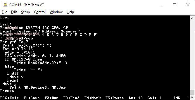 When I run the program, I got this 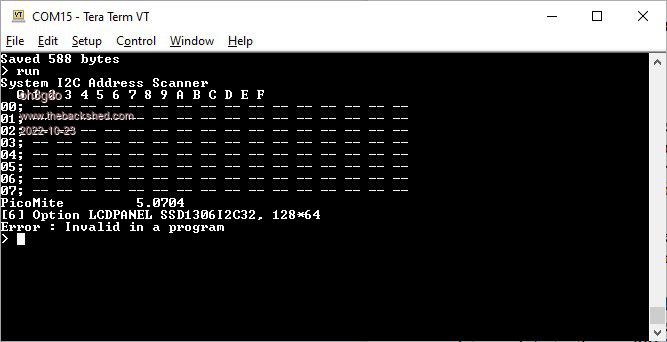 I have no 10k upload resistors to 3.3V. I tested the other LCD, but the result was the same Pekka |
||||
| phil99 Guru Joined: 11/02/2018 Location: AustraliaPosts: 3325 |
The initial setup of OPTION SYSTEM I2C GP0, GP1 OPTION LCDPANEL SSD1306I2C, L, 0 is done once and must be done at the command prompt, not in a program. It is saved in flash memory and remains resident. To see what Options have been saved, at the command prompt type OPTION LIST The output should include:- OPTION SYSTEM I2C GP0, GP1 OPTION LCDPANEL SSD1306I2C, L, 0 The System I2C Address Scanner should then show address 3C |
||||
Grogster Admin Group Joined: 31/12/2012 Location: New ZealandPosts: 9997 |
The "128*64" part of the command tacked on the end of line 6, is invalid syntax also. There are two commands you can use - OPTION LCDPANEL SSD1306I2C for the 128*64 resolution, or OPTION LCDPANEL SSD1306I2C32 for the 128*32 resolution. See PicoMite manual, page 43 and 44. Smoke makes things work. When the smoke gets out, it stops! |
||||
| oh3gdo Regular Member Joined: 18/11/2021 Location: FinlandPosts: 47 |
phil99, Thank you for your help, but because am starter, I can't change OPTION. When I start to move it, it says Error: Display already configured >Option list Option System I2C GP0,GP1 OPTION Autorun ON OPTION LCDPANELSSD1306I2C, LANSCAPE. So How can I change OPTION? I try to find this in manual, but I can't find it. == I have other problem. How I save my program to PC and how I load PC programs to PICO? I found from manual that I can use Xmodem F11 Receive and Xmodem F12 to send, But need I an external Serial connection or how I configure TeraTerm? Pekka |
||||
| oh3gdo Regular Member Joined: 18/11/2021 Location: FinlandPosts: 47 |
I found OPTION CLEAR from manual, but it didn't work. Pekka |
||||
TassyJim Guru Joined: 07/08/2011 Location: AustraliaPosts: 6549 |
Please ask your questions in thew correct sub-forum. WE don't all look here... To clear options OPTION RESET To save your program to the PC with TeraTerm start a capture in TeraTerm, (File/Log...) LIST ALL end capture in TeraTerm and you have your program saved... Jim VK7JH MMedit |
||||
| phil99 Guru Joined: 11/02/2018 Location: AustraliaPosts: 3325 |
First don't use OPTION Autorun ON until you have everything working properly Type OPTION Autorun OFF Xmodem F11 Receive In TeraTerm click File > Transfer > XMODEM > Send Then choose your program Xmodem F12 Send In TeraTerm click File > Transfer > XMODEM > Recieve Then type a name for it. Your output from the Address Scanner does not show any I2C device, so you must get that sorted out first. Are GP0, GP1, 3.3V and Ground all connected to the right pins? Check with a multimeter. As OPTION SYSTEM I2C GP0, GP1 does show after OPTION LIST there must be an error somewhere else. If there is a mistake remove it with OPTION SYSTEM I2C DISABLE. Then type OPTION SYSTEM I2C GP0, GP1 <Enter> Individual Options can only be changed by first deleting the old one. OPTION LCDPANEL DISABLE Then OPTION LCDPANEL SSD1306I2C, L, 0 <Enter> Type OPTION LIST <Enter> again to make sure it is all correct. You can then run the "System I2C Address Scanner" program again, (without any Options in it) it should then show Address 3C That will indicate the Pico and the display can communicate. Now you can try sending it some commands. Text 5, 5, "Hello World" Edited 2022-10-24 09:51 by phil99 |
||||
| oh3gdo Regular Member Joined: 18/11/2021 Location: FinlandPosts: 47 |
Phil99 Thank you for your help again. This File Transfer is sill unclear. I can press F11 or F12 and the Teraterm answers XMODEM Receive or XMODEM Send, but how I can send or receive? I have used this XMODEM about 40 years again, but then we had the receive end and the transmitter end by a modem. If I try to use Teraterm, it already in use, how I can take other connection? When I try to use other Teraterm, the com-port is already in use. == I have still some problem in my I2C LCD. Measure by oscilloscope the I2C signals, I see 8 pulses in the SCL wire and one bigger down pulse sat start and then two smaller pulses at end of I2C command. The test doesn't show any I2C address. But now when I run with 10ms all the test, I got half of Hello, so the upper part of this word. I try to write test to other pats, but all words come only upper part. Anyway this is a great improvement. Pekka |
||||
| phil99 Guru Joined: 11/02/2018 Location: AustraliaPosts: 3325 |
That you can get something on the LCD is good news, though why the address scanner doesn't show anything is a puzzle. Edit. Just noticed you have a typo in your picture of the scanner addr = y*16+1 should be addr = y*16+x ' calc address I don't know why only part of the screen is working. Post a question on the Microcontrollers and PC Projects Forum page. More people with more knowledge will see it there. Note @Grogster's comment "There are two commands you can use - OPTION LCDPANEL SSD1306I2C for the 128*64 resolution, or OPTION LCDPANEL SSD1306I2C32 for the 128*32 resolution." "This File Transfer is sill unclear. I can press F11 or F12 and the Teraterm answers XMODEM Receive or XMODEM Send, but how I can send or receive?" You only need to start TeraTerm once. It is the communication link between XMODEM in the Pico firmware and XMODEM on the PC. F11 and F12 only start XMODEM in the firmware at the Pico end, to start XMODEM on the �computer end use the mouse to click on "File" at the top left corner of the TeraTerm window use the opposite function (Send at one end, receive at the other). Press F11 for Xmodem Receive on the Pico For XMODEM Send on the PC Mouse click File > Transfer > XMODEM > Send Then choose your program Press F12 for Xmodem Send on the Pico For XMODEM Receive on the PC Mouse click File > Transfer > XMODEM > Receive Then type a name for it and click save. Another way to transfer to the Pico is with AUTOSAVE. Copy the text of your program from your editor to the clipboard (eg Notepad - Ctrl-A Ctrl-C) then in TeraTerm press F10, AUTOSAVE will start. Click the right mouse button then OK. To terminate the transfer press Ctrl-Z. You should then see "Saved 3667 bytes" or similar. To copy from the Pico to your editor in TeraTerm press F3 to LIST your program, use the mouse to highlight all the text then press Alt-C. In your editor press Ctrl-V. Edited 2022-10-25 17:26 by phil99 |
||||
| oh3gdo Regular Member Joined: 18/11/2021 Location: FinlandPosts: 47 |
phil99 Thank you, now I understand how to copy PikoMite program to PC. So I have to press F12, paste the list by pressing mouse the copy area and take the copy area to Notepad in PC. Was this right? Thank you that you found error in my LCD address program. Now it works. == I have still problem using NTC (10k to 3.3V and NTC to ground) I am using it to measure the temperature. I am using ADCREF to 3.3V, but I didn't get the right resistor voltage. It is 2.822V Well I try to find a problem. Pekka |
||||
| phil99 Guru Joined: 11/02/2018 Location: AustraliaPosts: 3325 |
"So I have to press F12, paste the list by pressing mouse the copy area and take the copy area to Notepad in PC. Was this right?" No, XMODEM and Copy / Paste are two different methods of transferring a program, there is also the one described above by TassyJim. "To save your program to the PC with TeraTerm start a capture in TeraTerm, (File > Log...) Type LIST ALL end capture in TeraTerm and you have your program saved.." "I have still problem using NTC (10k to 3.3V and NTC to ground)" Perhaps your thermistor is 100k? I only used 10k as an example. Measure it's resistance when it is at about 25 deg. C with a multimeter. Choose a resistor with a similar value to that reading. Eg if the thermistor is 4.9k at 22 C then a 4.7k resistor will be close enough. Once you know the two values put them in the program. |
||||
| oh3gdo Regular Member Joined: 18/11/2021 Location: FinlandPosts: 47 |
Phil99 Now I found a right save part of Teraterm. I have tried to send a file from PC to TeraTerm, but not yet find. Thank you. == I have used my 10k NTC measurement parts about 10 years, but in CCS c-language. I works perfectly. Now I found a problem in Log(Stainhart) part. It seems not working at all. I looked manual,but I cant find log function at all. Here is my program. I use 10k NTC and it has BCoefficient 4000, 25C is nominal temperature == SetPin 31, AIN ADCx = Pin(31) I= (3.322-adcx)/10000 Resistance =Adcx/I Stainhart= Resistance/10000 Stanhart = Log(Stainhart) Stainhart = Stainhart /4000 Stainhart = Stainhart +1/(25+273.15) Stainhart = Stainhart-273.15 == But log function doesn't seems to work Stainhart = 273.15. I should be about 20C Pekka |
||||
| phil99 Guru Joined: 11/02/2018 Location: AustraliaPosts: 3325 |
LOG() seems to work for me, ln e = 1. > Print log(2.71828183) 1.000000001 > Using R1 = 10000 ' series resistor beta = 4000 'thermistor coefficient R0 = 10000 'thermistor reference resistance T0 = 25 'thermistor reference temperature Vs = 3.322 'Supply voltage Vin = 1.661 'ADC voltage in this Ra = R1 * Vin / (Vs - Vin ) ' Calculate resistance Temp = 1/(1/(T0+273.15) + Log(Ra/R0)/beta)-273.15 ' Calculate temperature I get > R1 = 10000 : Vs = 3.322 : Vin = 1.661 : beta = 4000 : R0 = 10000 : T0 = 25 > Ra = R1 * Vin / (Vs - Vin ) > ? Ra 10000 > Temp = 1/(1/(T0+273.15) + Log(Ra/R0)/beta)-273.15 > ? Temp 25 > Which is correct. |
||||
| oh3gdo Regular Member Joined: 18/11/2021 Location: FinlandPosts: 47 |
phil99 You right, I was searching LOG10 MATH(LOG10 x), but it was right LOG(x= 'Pico Pi NTC10k resitor to 3.3V is 10k, NTC has Bcoefficient 4000, using adc0 in pin31 Option explicit Dim ADCX As float Dim stainhart As float Dim Res As float Dim I As float SetPin 31,Ain ADCX= Pin(31) I=(3.3-ADCX)/10000 RES = ADCX/I Stainhart = RES/10000 Stainhart=LOG (Stainhart) Print "Math(log10", Stainhart Stainhart =Stainhart/4000 Print "Stainhart/4000", Stainhart Stainhart = Stainhart + 1/(25+273.15) Print "Stainhart + 1/(25+273)" ,Stainhart Stainhart = 1/Stainhart Print "1/Stainhart",Stainhart Stainhart =Stainhart - 273.15 Print "Temp=", Stainhart,"C" This gives 22.4898C == I found also how to upload a PC file to Teraterm When the Edit is off, write in Teraterm: Xmodem Receive The look in Teraterm File/Tansfer/Xmodem/Send Then select file with PC, which should to send the TeraTerm == I have to search SSD1306 ( it is 0.9" height) LCD. Why it works only half? Pekka |
||||
| phil99 Guru Joined: 11/02/2018 Location: AustraliaPosts: 3325 |
"I have to search SSD1306 ( it is 0.9" height) LCD. Why it works only half?" As I don't have one of these you need to post this question on the Microcontrollers and PC Projects Forum page, not on the Windmills forum. More people with more knowledge will see it there. Click on "Forum Index" then "Microcontrollers and PC Projects" Edited 2022-10-27 07:34 by phil99 |
||||
| The Back Shed's forum code is written, and hosted, in Australia. | © JAQ Software 2026 |
