
|
|
Forum Index : Windmills : Progess photos
| Page 1 of 5 |
|||||
| Author | Message | ||||
JimBo911 Senior Member Joined: 26/03/2009 Location: United StatesPosts: 262 |
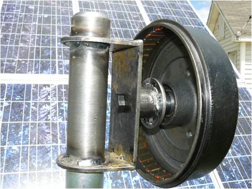
Here are some pics of the progress I have made on my mill. Please all comments welcome. 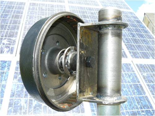
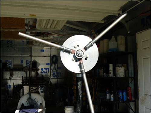
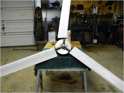
Jim |
||||
oztules Guru Joined: 26/07/2007 Location: AustraliaPosts: 1686 |
Hmmm someones got a lathe.... and they aren't afraid to use it either 
Nice clean looking design. I can't see how you are going to control it though (furling??). Apart form that a very clean and simple system. I like it 
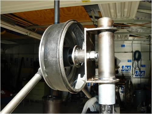
I would think that it would be good insurance to allow about a 5 degree uptilt to keep those lovely blades away from the tower. Either increase the length of the lower bracket or decrease the upper bracket (may get the nut too close to the yaw tube though). This will be the difference between a blade fault causing concern, and a blade fault causing disaster in a storm event. Keep up the good work.... and the commentary.... ....oztules Village idiot...or... just another hack out of his depth |
||||
fillm Guru Joined: 10/02/2007 Location: AustraliaPosts: 730 |
Nice work Jim , you have come up with a good hub design for the pvc blades , are you going to weld or bolt the angle retainers for the pipe stubs . One thing , how are you going to get blade offset for furling , and by the looks your blades will be 350mm + from your pole , this will give a fair amount of gyro torsion on the blades when yawing but it all looks very well built and designed with thought ....Well Done..Phill... PhillM ...Oz Wind Engineering..Wind Turbine Kits 500W - 5000W ~ F&P Dual Kits ~ GOE222Blades- Voltage Control Parts ------- Tower kits |
||||
| JimBo911 Senior Member Joined: 26/03/2009 Location: United StatesPosts: 262 |
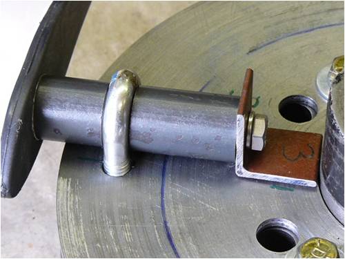
Thanks guys for your replies it really does mean a lot to me. As you can tell I am new to building mills. Oztules Yes I like my lathe I found it hiding in the basement of an old YMCA building some years ago in down town Chicago and made a deal with the wrecking contractor it took some doing to get it home. I did think that I may have a problem with the blades running to close to the support mast or tower. Not sure just how much flex the blades will have during high winds. I did place the mill in some mild breezes a couple of days ago and was very happy to see how she just took right off and never really wanted to stop spinning. (no load of course) that REALLY put a smile on my face. I didn't really have enough clearance for the spindle mounting bolt (only four threads) so I had to change it to a stud arrangement, had me scratching my head for awhile thinking what a dumb ass. In your opinion how much clearance do the 4 foot (1.22 meters) blades need to be from the mast or tower. Phill All ways good to hear from you. I was hoping to see how you mounted the blades on your AX mill before attempting to mount mine. I went ahead and welded the angles to the hub plate. It was kind of scary cause after spending lots of time machining the hub plate I didn't want the heat to warp it. The blade mounting stubs are 8 inches (203 mm) from the center line of the yaw tube, however the blades run around 139 mm (5.5 inches) from the mast. So after comments from both you and Oztules I take it that I need more clearance (off set) or space between the spinning blades and the mast or tower to make sure all is well under high winds. Again thanks for your input I want my mill to work properly. After all the time Ive spent in the shop my women is starting wonder what the hell happened to my Libido.  Jim |
||||
| fillm Guru Joined: 10/02/2007 Location: AustraliaPosts: 730 |
Hi Jim , Firstly , sorrie I havn't done the pictures of my blade hub design , but I think you have done very well and looks strong . I would not have welded the angle onto the plate first up untill the tip run out and tip to tip distance is spot on .. Like OZ has picked up the clearence at the tip to the pole can be increased by raking the hub back a few degrees . By looking at your pics I thought the clearance wold have been a lot more than 139mm . Off set is the distance from the yaw bearing centre to the blade rotor centre line which gives the force required to overcome the tail weight and furl at a certain wind speed to protect the mill from destruction , by the looks of yours it has no furling designed into it or are you going with a mechanical brake . You will not be able to stop a single stator F&P electrically when the wind is howling . If you search for a post " Furling - getting it right " it shows pics on setting off set and how it works .. And women just don't understand about a man and his mindmill  PhillM ...Oz Wind Engineering..Wind Turbine Kits 500W - 5000W ~ F&P Dual Kits ~ GOE222Blades- Voltage Control Parts ------- Tower kits |
||||
| JimBo911 Senior Member Joined: 26/03/2009 Location: United StatesPosts: 262 |
Hello Phill Thanks for your quick reply. I have known about off set for sometime now and shouldn't have any problem off setting my mill. I did not build my mill with any off set at this time because I have noticed that a lot of commerically built mills do not have any noticeable off set on there machines ie Bergy, South West etc. I will do as you and OZ have suggested and put some uptill to my blades. Again I also have to say that I am new at building mills and what you and OZ have said will most likely be correct. Thanks for your input. Jim |
||||
| oztules Guru Joined: 26/07/2007 Location: AustraliaPosts: 1686 |
Hi Jim... You asked "In your opinion how much clearance do the 4 foot (1.22 meters) blades need to be from the mast or tower. "......answer: enough so it will not hit the tower...no matter what is going on at the time. It is not just the air pressure pushing on the blades in a high wind, it is the accompanying gusts, and the torque from gyro moments when rough and unruly yawing is happening... and this can also get the wind at angles to the blade that we didn't consider... ie it "digs " into the wind at an odd angle that exacerbates the flexing of the blade... or all things happening at the same time. So the best plan is to put maybe 5 degrees or so pitch. This will not change it's wind catching ability in almost any way. You need to get off wind by maybe 25 degrees or more to get any meaningful loss of power. This means cheap simple insurance. My blades are about 2'6" away from the tower at the tips, but are 2m long timber blades (4M diameter.. yours 2.4M). When the wind is up and it is spinning at silly speeds, this clearance feels good. You must consider the furling problem before putting this thing up in the air. At this stage I see none. It may mean that you need to make another(new) yaw tube, and just weld an offset beam to your current yaw tube(which ceases to become a yaw tube and becomes a mill head only)... and incorporate the 5 degree uptwist at the same time to the new yaw tube...(and maybe even a 5 degree side twist to put the mill head forward of the yaw tube too) This will save you having to "unweld" the bottom bracket and lengthening it. I'm guessing that a 4"-5" offset(center to center) between the new yaw tube and the now up-turned turbine head should be enough. Phil will have a much better idea, as he is familiar with the torque of the F@P alternator (yes it makes a real difference as to how the alternator uses the wind and the furling needs) .........oztules Village idiot...or... just another hack out of his depth |
||||
| JimBo911 Senior Member Joined: 26/03/2009 Location: United StatesPosts: 262 |
Oztules As far as I am concern you and Phill are correct that's why I posted pics asking for comments. I will follow your instructions and make the appropriate changes. Will post more pics when completed. 
Thanks Phill Any ideas on the amount of off set I should use? F&P with neo's?? Jim |
||||
| fillm Guru Joined: 10/02/2007 Location: AustraliaPosts: 730 |
Jim Off set has no relation to F&P with neos it is the blade dia and a whole lot of other variables eg- tail weight , tail hinge angles ( side & back ) , the distance forward of the pole ( clearence ) in my opinion is best kept to a safe minium , with the PVC blades @ 2.4m dia with s/s tubes inside would be very rigid . The further away you get from the tower will also impact on the tail force required to keep your blades as square to the wind as possible , the offset changes as the blades get angled to the wind , causing the mill to be in a semi furled position when full wind to power extraction is needed . The further you get away from the centre of the yaw bearing the more imbalance you get when the furling point is almost reached , this can also cause a very savage furl which is not good . I run mine at 250 to 300mm with 2deg rake back , but I have 3.2mt blade dia and have never seen them come close to hitting the pole . As far as how much off set , I make mine adjustable 0 - 200 mm , then build your tail and tail pivot and set the tail pivot point angles by trial and error with a spring gauge at 100mm offset . I set mine at 10-12 kg furl moment @ 100mm , this would be less for a smaller dia . I did use the basic caculation for (force on a given dia )in furling explained on the home page but I ended up with a furl moment of 12klm when I put it up when I did the calcs on 35 klm . The head scratching is about to start again ....Phill PhillM ...Oz Wind Engineering..Wind Turbine Kits 500W - 5000W ~ F&P Dual Kits ~ GOE222Blades- Voltage Control Parts ------- Tower kits |
||||
| JimBo911 Senior Member Joined: 26/03/2009 Location: United StatesPosts: 262 |
Thanks Phill I have lots of work ahead of me but it's all good! Will keep you guys posted. See you soon. Jim |
||||
| Robb Senior Member Joined: 01/08/2007 Location: AustraliaPosts: 221 |
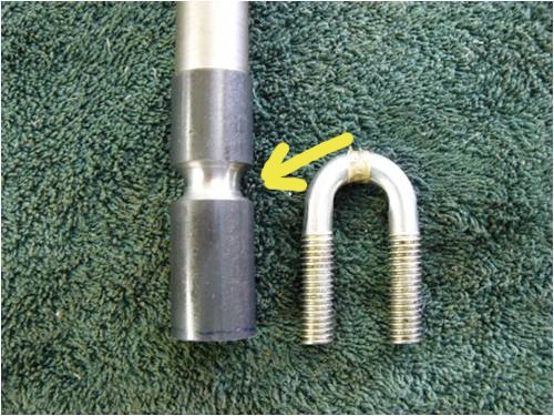
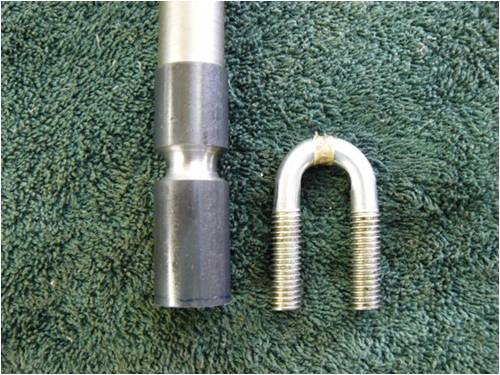
So thats the point were all the flexing is likely to be greatest and its now thiner than before. A bit like tare in the perforated line? I don't mean to be a killjoy but it just jumped out at me as a problem waiting to happen. |
||||
| Gizmo Admin Group Joined: 05/06/2004 Location: AustraliaPosts: 5187 |
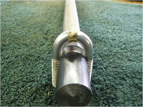
I have to say I agree with Robbon this one. I think the flexing and forces at this point will break the rod. By machining the grove,you've reduced the rod diameter to what looks like about 15mm, at the point where its under most stress. I would like to see another U-bolt further out, on a section of the rod that hasn't been machined. Or maybe machine a new grove, but only 1mm deep this time, it will still hold. Just my view, I do tend to over engineer my builds. Glenn The best time to plant a tree was twenty years ago, the second best time is right now. JAQ |
||||
| Gizmo Admin Group Joined: 05/06/2004 Location: AustraliaPosts: 5187 |
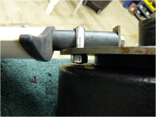
Or at least add a cable retainer like this, but on the outside of the U-bolt near the blade. 
I would like to see this on more builds, it means if there is a failure, the blade wont leave the scene at a dangerous speed. I've used a electrical terminal strip to clamp the cable ends together, not a good practice that I should replace with something better. 
Glenn The best time to plant a tree was twenty years ago, the second best time is right now. JAQ |
||||
| Dinges Senior Member Joined: 04/01/2008 Location: AlbaniaPosts: 510 |
[quote=Gizmo]Just my view, I do tend to over engineer my builds.[/quote] Sorry Glenn, but looking at your picture, I beg to differ.... Firstly, as you've stated yourself, the electric connector is very, very much too small for this function! In my R/C model days, we used that trick (electric connector) to connect the push-rods of model a/c. And even in that function, which is a very much lower load than in your case (should they actually be stressed, i.e. in case something goes wrong), I thought it was a dodgy solution. Secondly, the cable is way too thin. I guess it's about 1 mm diameter, so has a cross-section of .75 mm^2; assuming the steel cable has a tensile strength of 500 N/mm^2, that'd be 375N (38 kgf) before the cable would break.... (this is assuming the electrical connectors hold) If you had used cable of 6-8mm, and properly fastened it to the hub too, I'd agree with your 'overengineering' statement,  . But the cable you've used would be only acceptable to lock a nut or a similar low-load task, not serve as a backup fail-safe in case the other fasteners fail. . But the cable you've used would be only acceptable to lock a nut or a similar low-load task, not serve as a backup fail-safe in case the other fasteners fail.
And whilst I'm at it... looking at that picture, I see you're not using locked nuts (the 3+1 nuts in the middle, not the ones welded onto the blade shafts). No mechanical locking by locking plates or wires, or nylocks. Maybe you've used Loctite on the threads? Please keep in mind that for dynamic loads as in windmills the locking of nuts and bolts is an absolute requisite if you want things to stay put over time. A locking washer is no (and I repeat, NO) good in such situations. Peter. (who's fearing suspension of his account ) |
||||
| Gizmo Admin Group Joined: 05/06/2004 Location: AustraliaPosts: 5187 |
Points taken. Still you have to admit, there is a lot holding that rod onto the hub, no way its going to come adrift. I thought lock washers were OK? Glenn "Glenn's mouse pointer hovers over the Delete User icon on Dinges account" The best time to plant a tree was twenty years ago, the second best time is right now. JAQ |
||||
| Dinges Senior Member Joined: 04/01/2008 Location: AlbaniaPosts: 510 |
[quote=Glenn]"Glenn's mouse pointer hovers over the Delete User icon on Dinges account"[/quote] [quote]I thought lock washers were OK? [/quote] Dinges nods fervently and agrees with Glenn that lock washers are more than adequate, honestly! Seriously though, this video shows it dramatically: http://www.youtube.com/watch?v=mgwmuZuJ02I&feature=PlayList& p=6F40964F411B5ABC&playnext=1&playnext_from=PL&index=1 It's a commercial video, trying to sell a product, but still. Personally I wouldn't use anything but locking wire, locking plates, castle nuts or Loctite for applications as windturbines. Even though Nord-Lock would prefer me to use their products.... Dynamic loads (as encountered in windturbines) are nasty. Not just regarding fasteners, but also regarding fatigue (which is why the solution the original poster used for fixing his blades, with a deep groove in the shaft for the U-bolt, is doubly bad: the kerf is not just a simple extra weakness but actually an initiating point for fatigue cracks. Fatigue is only an issue with dynamic loads, as encountered in windturbines for example. Static loads are much simpler and more forgiving of mistakes in this respect) Peter. |
||||
| Gizmo Admin Group Joined: 05/06/2004 Location: AustraliaPosts: 5187 |
Good to know about the lock washers, maybe we need a "best practices" page? Glenn "Glenn slowly moves his mouse pointer away from the Delete User icon on Dinges account" The best time to plant a tree was twenty years ago, the second best time is right now. JAQ |
||||
| Janne Senior Member Joined: 20/06/2008 Location: FinlandPosts: 121 |
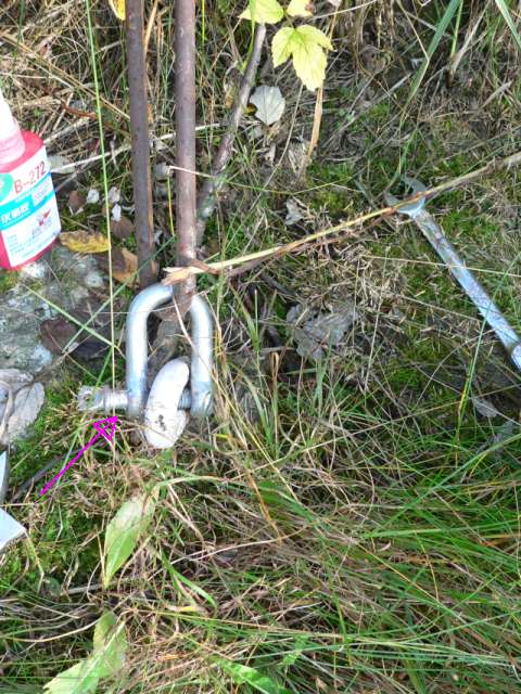
I argee on the need for locking most nuts and bolts on a turbine, especially those, that cannot be tightened to a good preload torque. For example, shackles, and the bolts that are compressed against wood need to be locked down to prevent them coming undone. However, i've noticed, that on nuts and bolts that are tightened against steel, thus allowing good preload torque, there is no problem with them coming loose. This picture should serve as a reminder why locking the fasteners is important 
About the groove on the blade shaft, it really doens't need to be that deep. After all, the purpose of the u-bolt is to hold down the blade to the hub by friction, if it moves against the u-bolt, then i see that it has already failed. If at first you don't succeed, try again. My projects |
||||
| GWatPE Senior Member Joined: 01/09/2006 Location: AustraliaPosts: 2127 |
Hi janne, this looks like a cheap unrated D-shackle as well. Rated components are usually forged metal and are painted with a colour coding. Mousing wire is cheap, but still has to be checked. It really depends on how well the system is balanced and how much the guy system moves, as to what will become a problem. I have seen 2 windmills fail due to shackles unwinding, or turnbuckles unwinding. Gordon. become more energy aware |
||||
| JimBo911 Senior Member Joined: 26/03/2009 Location: United StatesPosts: 262 |
Thanks guys for all your responces, ideas and thoughts. Jim |
||||
| Page 1 of 5 |
|||||
| The Back Shed's forum code is written, and hosted, in Australia. | © JAQ Software 2026 |
