
|
|
Forum Index : Windmills : 1.5kw 6 pole motor conversion
| Page 1 of 4 |
|||||
| Author | Message | ||||
Smart Drives Senior Member Joined: 06/07/2009 Location: AustraliaPosts: 115 |
After a lot of procrastinating i have had a friend put my motor on his lathe and take 22mm off the rotor. This left the diamter at 84mm. I wrapped some paper around the rotor and the final measurements are: 267mm x 120mm. The picture is to scale. The magnets i want to order are 46mm x 30mm x 10mm. I understand that since the stator has 36 slots i should use a 10 degree skew. It appears that i can only fit 12 magnets on the rotor. Will the way i have set out the magnets create a cancelling effect ? or is there a formula i can use to lay them out ? (maybe another size magnet) 
Any input appreciated. Thanks. Cameron. All smart drive parts sold Custom built turbine parts on Multicam flatbed CNC Router |
||||
| Gizmo Admin Group Joined: 05/06/2004 Location: AustraliaPosts: 5187 |
Hi Cameron Took me a while to work out what that picture was of, at first I thought the image resizing code was freaking out. You didn't mention how many poles the motor has, 2 or 4, 6 or even 8. If your not sure you can work it out from the RPM. Is the RPM marked on the tag? Glenn The best time to plant a tree was twenty years ago, the second best time is right now. JAQ |
||||
| Smart Drives Senior Member Joined: 06/07/2009 Location: AustraliaPosts: 115 |
Its in the heading "6 pole conversion". which is 945rpm i think,. Thanks. Cameron. So this means i put magnets in every 60 degrees on the cylinder. How wide can my magnet be ? Ans: no wider than 3 slots on the stator (36 slot stator)before you skew it 10 degrees. All smart drive parts sold Custom built turbine parts on Multicam flatbed CNC Router |
||||
| Smart Drives Senior Member Joined: 06/07/2009 Location: AustraliaPosts: 115 |
A few pics of the project 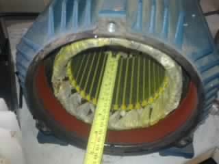
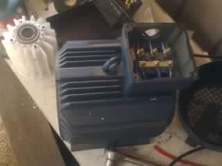
All smart drive parts sold Custom built turbine parts on Multicam flatbed CNC Router |
||||
| Smart Drives Senior Member Joined: 06/07/2009 Location: AustraliaPosts: 115 |
I have decided to use 6 large magnets, 75mm x 25mm x 12mm , if i can find them in NeFeB with an epoxy coating for durability. The picture of the magnet layout above will have slightly larger gaps now and only 1 magnet per pole. Cam. I found some 75mm x 25mm x 12.5mm mags with 45kg lifting strength , these should do the job nicely. getting the rotor in and out might be interesting though. All smart drive parts sold Custom built turbine parts on Multicam flatbed CNC Router |
||||
| GWatPE Senior Member Joined: 01/09/2006 Location: AustraliaPosts: 2127 |
The need for a lifting eyelet indicates that his will be a substantial object on top of the pole. Any idea of the finished alternator weight? Gordon. become more energy aware |
||||
| Smart Drives Senior Member Joined: 06/07/2009 Location: AustraliaPosts: 115 |
I would guess it weighs about 25 - 30kg, I am doing this project to learn everything that can go wrong in preparation for an 4.5kw 8 pole motor conversion. I am planning to put this motor on a 6m x 100mm dia. pole. The next project (due to weight) might end up as a VAWT. I'm getting the steel rotor made this week, so more pics soon. Yes if anyone is wondering why i lathed down the aluminium rotor i wasn't aware at that time it had to be steel. More mistakes to come soon  stay tuned. stay tuned.
Cam. All smart drive parts sold Custom built turbine parts on Multicam flatbed CNC Router |
||||
| Gizmo Admin Group Joined: 05/06/2004 Location: AustraliaPosts: 5187 |
Looks like a fun project Cam. I have a few induction motors just waiting for conversion. I was going to try standard ceramic magnets to keep the costs down, and I do wonder if using neo magnets might be saturating the stator. Keep us posted. Glenn The best time to plant a tree was twenty years ago, the second best time is right now. JAQ |
||||
| Smart Drives Senior Member Joined: 06/07/2009 Location: AustraliaPosts: 115 |
Maybe if i do 2.5mm air gap that will keep the saturation down ? Cam. All smart drive parts sold Custom built turbine parts on Multicam flatbed CNC Router |
||||
oztules Guru Joined: 26/07/2007 Location: AustraliaPosts: 1686 |
Gizmo and Cam, More magnet is more goodder. You will suffer more iron loss, but the performance in every other way will be improved. I assume that you won't be rewinding the stator... so I expect it to be higher impedance than you would otherwise want. If we saturate the iron, it will look like air gap anyway, as after it is saturated, any extra flux will behave as if the iron wasn't there..... what might this mean? Well, a bit more flux will link the coils, and this will lower the turns/volt.... lower rpm performance... very helpful. A second more important thing I am guessing is (and Herb will keep me honest here I suspect), is that with the stronger magnets, you push back the current limiting aspect of the generator... ie it will take more back MMF to interfere with the magnets for two reasons. 1. As the extra magnet makes the iron look more like air near the gap itself, it effectively makes a wider air gap. This makes it much harder for the back MMF to impinge on the permanent magnets than would have happened with ceramics. 2. The magnets are much stronger now, and that means it will take more amp turns from the stator to interfere with their field... (added to the wider gap from 1). This means the effects of armature reactance will be lessened, as you need more amps flowing in the coils to react against the fields than before...... so more amps before current limiting and runaway sets in. I think these are worthwhile gains as I understand it. The other thing is that everyone else uses Neo's, in their conversions and that says something too. ............oztules Village idiot...or... just another hack out of his depth |
||||
| Smart Drives Senior Member Joined: 06/07/2009 Location: AustraliaPosts: 115 |
thanks oztules, No i wont be rewiring it. I will leave the gap as close to 1mm as i can . I will be slotting the steel shaft about 4mm deep so i can slide the magnets in to their exact position, I hope putting them in that far doesn't affect the flux. I will have a photo tomorrow. Cam. All smart drive parts sold Custom built turbine parts on Multicam flatbed CNC Router |
||||
SparWeb Senior Member Joined: 17/04/2008 Location: CanadaPosts: 196 |
Hi SmartDrives, Nice choice of motor to start with. I prefer motor conversions almost because the end result IS heavy. 
I am beginning to think that a measurable improvement can be made by using a solid steel rotor instead of turning down the original rotor with all its aluminum bars. It's sort-of obvious when you think about it - the magnetic field wants to make a continuous loop, but the aluminum bars don't carry the lines of flux from magnet to magnet like a cylinder of steel or iron would. I was rushed for my last motor conversion, and decided not to make a new steel rotor. The result is I'm a little disapointed by the battery-charge test results, and this is probably the reason, because I just turned the original rotor down to the size I needed, aluminum and all. Just to amplify Oztules's comments: saturation is GOOD. I will grant that it leads to a stiffer slow speed, but wind turbine blades do have enough torque to overcome this if you have enough blade chord, twist, and a reasonable airfoil cross-section, in my experience. Once the current starts flowing, a magnetic field gets set up against the magnets themselves, which is what ultimately limits the power that you can get out of a motor conversion. Putting as much magnet as possible to start with is the simplest way to deal with that. Keep in touch, we all will enjoy hearing about how the project goes. Steven T. Fahey |
||||
herbnz Senior Member Joined: 18/02/2007 Location: New ZealandPosts: 258 |
Hi Steven and Oztules Its great to hear the understanding of generater action reaction in the discusion. ie no talk of saturation as load increases but actually the other way round. Poles that can be saturated at no load will drive themselves out as load is increased. Herb |
||||
| Smart Drives Senior Member Joined: 06/07/2009 Location: AustraliaPosts: 115 |
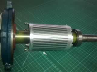
Magnets still haven't turned up, so here is a photo of the new rotor. Thanks SparWeb it appears from what you said that i can slot the magnets in as far as i like with no loss of power. 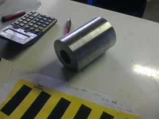
All smart drive parts sold Custom built turbine parts on Multicam flatbed CNC Router |
||||
| oztules Guru Joined: 26/07/2007 Location: AustraliaPosts: 1686 |
Eeeeek. [quote]Thanks SparWeb it appears from what you said that i can slot the magnets in as far as i like with no loss of power. [/quote] No.. As you sink the magnets down into the rotor steel, you make it easier and easier for the magnet flux to "short" from the front pole top to the back pole. If you make the air gap very very tiny, it will have much less effect, but with flat magnets in a circular stator, you will have a few more mm of gap in the center of the magnet face If you sink the magnets in a few mm, it will have very little effect, but the further you sink them, then less flux will jump through the air gap, and instead jump straight to the steel rotor... and so back to the back of the magnet. In the extreme case: If you sink them right in, the flux from the edges of the front face of the magnet will go straight to the rotor, and it will be a dash through the door to see how many more can jump from the inner regions of the front face to the rotor until the flux is so thick there, that the rest have to jump to the stator and do the generating task you wanted them to do. The harder you make it for them to short straight to the rear face from the front face, the more flux lines will be available to jump to the stator and so link the coils. ie sinking them is a retrograde step if overdone. It's no where near so bad in the induction conversions as in the axial flux, as the axial expects the flux to jump a much much larger gap, so is far more inclined to take shortcuts and leak to the next magnet... or if sunk, then into the rotor steel... or both....but conversions suffer from much lower transition speeds, so needs all the help it can get.... it's never simple Does that make any sense? ............oztules Village idiot...or... just another hack out of his depth |
||||
| Smart Drives Senior Member Joined: 06/07/2009 Location: AustraliaPosts: 115 |
Unfortunately it does make sense.... so would 4mm be to much ? Thanks. Cam. All smart drive parts sold Custom built turbine parts on Multicam flatbed CNC Router |
||||
| SparWeb Senior Member Joined: 17/04/2008 Location: CanadaPosts: 196 |
I'm sorry Cam, it seems you've seriously misunderstood what I meant. I'm not sure if Oztules has cleared it up for you either. You're asking about slotting the magnets into the rotor (the part which rotates). Your earlier question was about saturation in the stator (the part which is static). The two questions both go to the performance of the conversion, but they are separate subjects and we ara trying to tease them apart and talk about them separately. I'm just lucky I guess, I received a thorough education about magnetic fields in college, but it's not common experience to most people. If you want to learn more about how the field lines of a magnet are attacted to ferrous metals, and how they can be diverted in different ways, it would give you a better "gut feel" for what the magnets do when mounted inside these generators. If your motor had only 2-poles, then this diagram illustrates what happens. Aminated 2-pole 3-phase synchronous motor You can stop and start the animation (after it's fully loaded) by hitting ESC and F5. What you see are the poles of the rotor energized with a DC coil, but it produces a constant N-S going around. Close enough. As it turns you can picture it as a motor or as a generator. They are equal but opposite. The dots on the outside represent the intensity of the field at that point in the stator. Each phase is wound into the stator at different places. We see them only as two circles, so imagine the path of flux as lines from the N on the rotor flowing to the dot, then splitting left and right, flowing around the sides to the dot on the opposite side, then meeting up and going into the S pole. The magnetic field at any point in the stator goes from a strong N to zero to a strong S and back to zero every time the rotor goes around. It would happen 3 times per revolution if the rotor has 6 poles. Steven T. Fahey |
||||
| SparWeb Senior Member Joined: 17/04/2008 Location: CanadaPosts: 196 |
Just one more thing: In the animation, the plot on the left is a graph of magnetic flux, not voltage, not current. ...and the red circle on top is supposed to switch between having an "X" in it to a ".", but instead it has a bigger dot. Hey it's not my animation, but it's really useful for illustration of how magnetic fields work. You can try looking at some of the other animations on the website but I don't understand the half of them either! Steven T. Fahey |
||||
| GWatPE Senior Member Joined: 01/09/2006 Location: AustraliaPosts: 2127 |
Hi sparweb, I see no animation in the link you pvovided with IE8, but heh google chrome shows OK. The pic is not a good demo for the fields with NEO mags available for conversions. In this example, the magnet ends are as far apart as possible, and there is a short uniform air gap. This could be achieved with curved magnet ends in a multi pole alternator, but we are usually stuck with flat pole ends in a curved stator, with multiple poles. The flux lines tend to bunch at the edges of the magnets, and more can take the short cut around to the oposing pole by bypassing the path we want them to go through the stator. The bypassing can be to adjacent poles as well. In a motor conversion, when milling flat surfaces into the rotor, keep the alignment step to 1mm or so. This may result in 4-5mm of metal being removed at the max arc point. Gordon. become more energy aware |
||||
| oztules Guru Joined: 26/07/2007 Location: AustraliaPosts: 1686 |
Great animation Sparweb, but not quite descriptive for this application... but excellent for 3ph understanding. I can't find Dinges Femm of his conversion, so I will use this one from http://www.powercroco.de/magnetkreis.html. Smartdrives, look at this. It is opposite to a conversion, as it is a motor... but the magnets and rotor steel are on the outside, and the teeth are on the inside, but the same rules apply. 
In your case, this motor casing will be your rotor, and this armature teeth (2 of) will be your stator, and the magnets (2 of) will be your magnets. Note the 2 flux lines linking the magnets to each other, this indicates leakage, and is worse when the magnets are too close together... or the gap is big.... the flux will take the easiest path home. Note also, all the flux lines leaving the face of the magnet, return to the base of the magnet via a variety of paths... but they all must get there. No flux can go out without returning.... just like an electric circuit. The small lines jumping from the sides of the magnets back to the casing, are the ones we are interested in with regards to sinking magnets. If you can imagine sinking them, it is easier and easier to return via this short path, rather than jumping the gap and taking the long route. Once again, a skinnier gap will help keep them interested in jumping the gap, a wider one will deter them, and they will cheat.... and jump directly to the case, or the magnet next door.... but they will go somewhere.... follow every flux line to get the idea. 4mm should not change things too radically, as the air gap should be very small at the edges of the magnets... but less depth would be marginally better I think... Perhaps follow Dinges lead......if anyone knows what is going on inside these things... it is him and Sparweb. 
.............oztules Village idiot...or... just another hack out of his depth |
||||
| Page 1 of 4 |
|||||
| The Back Shed's forum code is written, and hosted, in Australia. | © JAQ Software 2026 |
