
|
|
Forum Index : Windmills : 1X6C 7 phase delta
| Page 1 of 2 |
|||||
| Author | Message | ||||
KarlJ Guru Joined: 19/05/2008 Location: AustraliaPosts: 1178 |
I think I'm getting carried away with myself here but here goes. 7Phase = higher voltage output than the three phase. good. Voltage doubler/cap mod halve cutin rpm good Delta wiring more power higher cutin good /bad. Will the improvement (V) from a 7phase outweigh the drawback of delta or at least offset it enough to warrant the effort. Would the cap size be the same? Also had a win today in hard rubbish collection. Scored the following outdoor enclosure for electricals at turbine end. tower for dummy set-up (hills hoist) F&P 80S in perfect condition 8x 7' star pickets !! 2 x 1800W heating elements. Although I built an encapsulated resistor and mounted it in a PC power supply box, it has some limitations, ie at 48V 56x56/6 =522W but on the same token 522/56=9Amps which is more than they saw in original service. I should have cut in half not thirds and parallelled in the first place but they end up really long for 48V. Next idea is to just use 4or5 full size 1800W/2000W wired in series, that will give me the same resistance I aim for of 4-5 ohms and will easily handle anything i can throw at it cut my first bearing out of the tub too. a normal wood hand saw worked a treat, took about 5mins. Karl 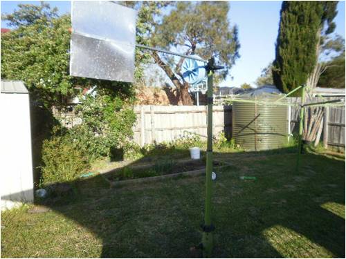
 Luck favours the well prepared |
||||
| Gizmo Admin Group Joined: 05/06/2004 Location: AustraliaPosts: 5187 |
Hi KarlJ You cant have a 2X7C in 7 phase, only 3 phase. The 7 phase option means you have to use a special magnet hub, and wiring it up as a delta would be just plain scary. Is this something you have already wired up, can you post a photo of the stator, we might be able to see how you've done it. How many wires are there from the stator? Good score from the rubbish. Glenn The best time to plant a tree was twenty years ago, the second best time is right now. JAQ |
||||
| KarlJ Guru Joined: 19/05/2008 Location: AustraliaPosts: 1178 |
oops just realised this and changed the title. 1x6c 7 phase. I appreciate this means new magnet rotor, (which I dont have) delta scary..... why? Luck favours the well prepared |
||||
| Gizmo Admin Group Joined: 05/06/2004 Location: AustraliaPosts: 5187 |
Someone else might be able to help here. There was some discussion about 7 phase delta a year back, I seam to recall it wont work very well, but I could be wrong. Glenn The best time to plant a tree was twenty years ago, the second best time is right now. JAQ |
||||
Downwind Guru Joined: 09/09/2009 Location: AustraliaPosts: 2333 |
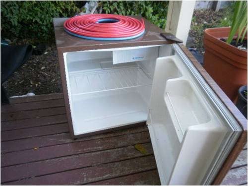
Keen to know how the fridge fits into the mill design? It no good anyhow there is no beer in it? Whats the lengths of the elements you have there and the rated wattage for the length. Good tip with the hand saw. Pete. Sometimes it just works |
||||
| KarlJ Guru Joined: 19/05/2008 Location: AustraliaPosts: 1178 |
These elements are 32 Ohm dishwasher variety. making 1800W A bit disappointing I expected they would be the same 24 Ohm as found in an oven. as Im going to need to find a ****load of them to get down to the 4Ohm. they are 1.5m long each. Fridge will become an electrical cabinet for CAPS and rectifiers out at the mill, seems a shame to gut it is only rated at 150W which with a little inverter would probably work as a car/garage fridge. I might put a new cable on it (was cut off) and see if it works. Luck favours the well prepared |
||||
| GWatPE Senior Member Joined: 01/09/2006 Location: AustraliaPosts: 2127 |
That fridge consumes 50% more power than my normal house fridge. 150W compared to 100W for my normal fridge, even at 25 years old. Cap cabinet is a good idea. Gordon. become more energy aware |
||||
| KarlJ Guru Joined: 19/05/2008 Location: AustraliaPosts: 1178 |
Fridge works like a champ..... plugged it in via the energy meter and it tells me it is drawing 0.5A at a power factor of 32 (whatever that means) and consuming 40-48W. I'm all for recycling but seems like a waste to cut it apart when it works just fine. Anyone want to swap a 50W fridge for an electrical cabinet of sorts -Im happy with almost anything waterproof. Karl Luck favours the well prepared |
||||
| Downwind Guru Joined: 09/09/2009 Location: AustraliaPosts: 2333 |
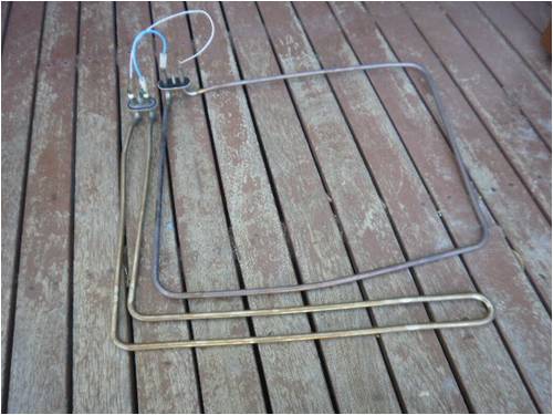
Hi Karlj, I am not sure what went wrong with you first attempt at cutting up a element into sections to make resistors. Doing a few calculations on the elements you have there ( 240 volt, 1800 watts, 1500mm long, 32 ohms) Tells me you should be able to get 3 resistors from each element. Each resistor would be around 5 amp at 56 volt or 280 watts. Putting 3 resistors in parallel with each other should give you 280 x 3 = 840 watts at 56 volts. I would expect this to be more than ample for your mill. So I ask what do you expect the max. output of the mill to be?? Working this out. 240 x 240 / 1800 = 32 ohm at 1500mm long. Lets say we want a 5 amp resistor at 56 volts. ( about half its max rating) 56 x 5 = 280 watts 56 x 56 / 280 = 11.2 ohm per resistor To work out our length per resistor. 11.2 / 32 x 1500 = 525mm This is near enough to 500mm for me so 1/3 of your element per resistor. The actual value of the resistor will vary some amount but it is not that important and will be somewhere near enough. You commented on the length required. This is why I bent the ones I done into a horse shoe. You can loose a 100mm in the bend and the height will be 200mm then. You could bend them around in a circle and loose the length fast. Do a test with a piece of wire and find a circle size that will work and allow for the ends to be longer for a couple of mounting legs. It is easy to wrap a element section around a piece of pipe. The dishwasher elements I think are the best to work with from the ones I played with. Have you had a look at the article on the front page of late, as Gizmo made one to, and used straight short lengths. You could do this and run a few in series and then parallel a couple of series blocks to get the overall resistor length down. As a sh�oot lot of elements wired together as you are thinking would be a lot bigger than 1 cut up element. I would keep the fridge and something else will turn up for a mounting enclosure Perhaps a microwave oven, glass front door to view things through, some ventilation, some thermal resistance, might need to put a waterproof roof on it. Also a couple of good magnets in the magnetron. I like your work and good luck. Pete. Sometimes it just works |
||||
| KarlJ Guru Joined: 19/05/2008 Location: AustraliaPosts: 1178 |
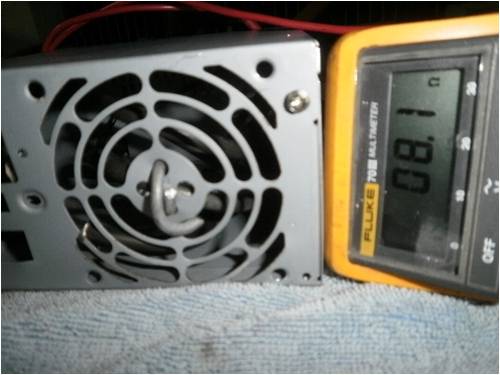
I was hoping for something in the region of 500W out of the single stator mill, I think Cameron said it was possible to get 600W out of a single stator, perhaps thats optimistic. Microwave....mmm brilliant! heaps of those in hard rubbish and to think I was ignoring them. Soon a Fillm dual stator mill. I was sizing the dump load to suit that, as many have said when it does go wrong..... so I was aiming for a dump load in the order of 1000W. I snapped a couple of the first elements whilst winding them around some pipe, perhaps the dishwasher ones are more malleable. I'll have another crack at it. Perhaps a 2nd microwave box with door removed to mount the next dump load.. As I dont have oxy set I'm left with using 1/2" copper pipe in small lengths and crimping them around the element on either side of the piece of steel. or some steel wire as shown to hold it in a PC power supply box but with it dissipating 390W (56x56/8.1) Also after reading OZtules effort with his heating elements in an ice cream bucket I could see the voltage rising to say 65+ giving 65x65/8.1 =520W Now anything like that kind of heat in a smallish space, I might as well put a pot on it and cook for dinner! Now there's an idea -mount dump load inside an oven if its blowing a gale and the grid is down at least I can make a roast dinner! Karl 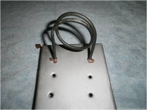
Luck favours the well prepared |
||||
| Downwind Guru Joined: 09/09/2009 Location: AustraliaPosts: 2333 |
Karl, Ok i typed this after reading the email and not looking at the posting. But will still post it all the same. Nice job on the resistor in the photo. serious meter. If you were a little closer i would come around for that roast dinner. Lamb or pork?? lol. Anyway what i had typed. I think I see the problem of why you are snapping the elements. There is a little trick in bending any tube and the same with an element. When bending something the force needs to be kept in close to the mandrel (in this case the pipe that you are bending around) This is why in the photo I show two pieces of � inch tube slid over the resistors and in close to the pipe former/mandrel. As you bend a little the tube will come in and hit on the pipe, stop and slide the tubes out a little and bend again then side the tubes out and bend again and so on. The most important part is to pull back on the tubes as you bend so as to hold the force against the pipe mandrel. The reason things snap is the element levers away from the mandrel in the centre of the bend, and starts to crimp then snaps. If you try the bend with some copper tube (as a test instead of the element) you will more than likely crimp it, because it has left the mandrel in the centre. The bend can be done and is not hard to do its just the method you do it in. Sorry at times I tend to take some of the things I do for granted as we all tend to. If I detailed every little step and why, it would take for ever and be a boring read. Another thought of looking at this. Place the pipe vertical in the vice. Centre the resistor up against the pipe, with a clamp or vice grips and gently clamp the centre of the resistor to the pipe so this point can not move away from the pipe. Then with the bits of tube slid over the resistor start your bend but bend evenly on both sides together, in stages as I said above. The vice grips should stop the resistor moving away from the pipe and it will not snap. Practice make perfection and once you master it you will be able to advise others how to do it as your way of explaining this might be better than mine. If you run into trouble again stop! and ask and I will try to work through this with you. Yes microwaves are everywhere often in rubbish, and we tend not to give them a second thought. The front control panel can make a good timer, as often has its own onboard power supply and a relay power switch output. Just wire it up, leave set on full power setting and enter time period press start and you have a countdown timer, it even beeps when done. They have a high power diode as well in a ceramic casing should you ever need one. I can see your misses cutting crook soon with all this junk you drag home. �It will come in handy darling� will only work for so long. ( Be warned ) Cheers Pete. Sometimes it just works |
||||
| KarlJ Guru Joined: 19/05/2008 Location: AustraliaPosts: 1178 |
my tip for the day is to leave one end with the factory terminal, at least thats one end you dont have to muck around with. Karl Luck favours the well prepared |
||||
marcwolf Senior Member Joined: 08/06/2009 Location: AustraliaPosts: 119 |
Hi Folks Sorry for being off air for so long.. Work and other issues. Tomorrow I will be getting my solar electric system installed so I can then put the wind generator project back into the foreground So you have a Hill's Hoist. Now if you can mount that hig up and horizintally with some added sails you have the basic for a decent windmill. Yours humorously Dave Coding Coding Coding.. Keep those keyboards coding.. RAW CODE!!!!! |
||||
| KarlJ Guru Joined: 19/05/2008 Location: AustraliaPosts: 1178 |
OK forget the 7 phase here is the rewire 1x7c star + 1x7C delta Did I get it right? 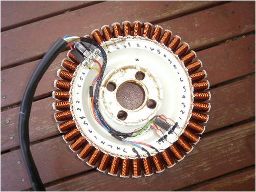
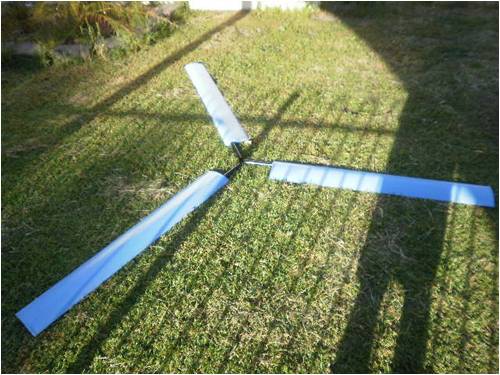
Blades / spinner on for a look..... 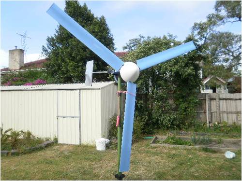
Tubes are fixed in the hub but tubes yet to be fixed to the blades, Trev's hub allows for no movement of pitch unless the hole through the blade is bigger than that in the hub allowing for only a small amount of change, I elected to make the holes size for size and i'll pitch the blades and rivet them on tomorrow. Balancing looks like its going to be fun (lack of space) and lack of tools per the site, but i'll have a go now that I have a spare shaft or two to cut up for the plug. Luck favours the well prepared |
||||
fillm Guru Joined: 10/02/2007 Location: AustraliaPosts: 730 |
Karl , I have found that the starts and finishes of the series should be in the rotation of the rotor , but I could be wrong and some will correct me if I am no dout . I wire one stator in star and one in delta with my dual , it gives good low wind performance and then the delta kicks in at rpm's over 150. PhillM ...Oz Wind Engineering..Wind Turbine Kits 500W - 5000W ~ F&P Dual Kits ~ GOE222Blades- Voltage Control Parts ------- Tower kits |
||||
| KarlJ Guru Joined: 19/05/2008 Location: AustraliaPosts: 1178 |
so for my star winding on the RHS I would pick the power from the other end (ie the one with the F&P connector between phases) and join where I cut it in half instead. I read somewhere else on the forum that you could effectively rectify from both ends. He called it an open delta. Aim is to be ready for a changeover to one of your mills when finances permit- run two sets of wire up the pole, the two voltage doublers etc. Theory for this one is "poor mans dual stator" I ended up with about 2.6m diameter, dad's jaw hit the ground -and this is just the beginning! tomorrow stop switches 4x 15A breakers and a 20A breaker for the 48V line to the house Luck favours the well prepared |
||||
| KarlJ Guru Joined: 19/05/2008 Location: AustraliaPosts: 1178 |
I like to call these heat horns.... 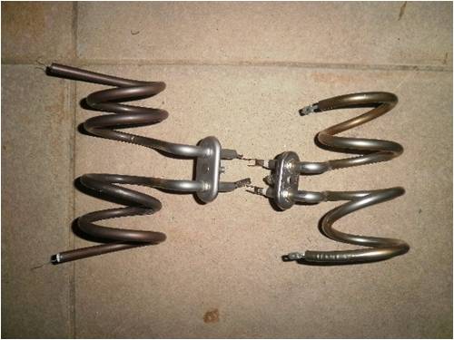
The slightly longer ones are 10.5ohms a side giving me 300-350W each. @ 56-60V The shorter ones (broke them again) are 6.5 ohms each. giving me 241W if wired in series. or if I wanted to use them as lightbulbs 480W each in parallel. so for starters I'll run the 10.5 ohm jobs in parallell. I like the premade mounting with this idea. Luck favours the well prepared |
||||
| Dinges Senior Member Joined: 04/01/2008 Location: AlbaniaPosts: 510 |
Sorry, nothing useful to add to this thread, but just wanted to show off after seeing Karl's nice resistors. 
A guy in NL was selling these power resistors, military new old stock; 7.1 ohm, 53W each, and very easy to mount. After I heard what the price was he wanted for one I bought them all, slightly over 100 pieces. For the price he asked for them I couldn't even buy one single power resistor in the store :-) 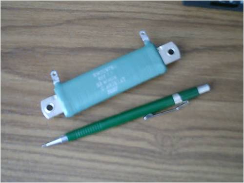
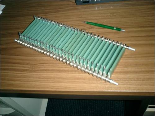
Needed them not for a dumpload but for the resistor part for a relaxation oscillator. Put 28 in a bank (will wire them in 4 switchable sections) for a total power of 1500W. I figure the other resistors will come in handy in the future too, perhaps for a dumpload even. "Better to have them and not need them than the other way around", the packrat in me said. Peter. |
||||
| KarlJ Guru Joined: 19/05/2008 Location: AustraliaPosts: 1178 |
next is a 48V toaster..... Luck favours the well prepared |
||||
| Downwind Guru Joined: 09/09/2009 Location: AustraliaPosts: 2333 |
Nice work with the resistors Karl. Looks like you stole them off rudedolf. It has me miffed why they are snapping on you as i wound one up like a spring at a fraction of the dia. you use and did not break it. I like your work. Pete. Sometimes it just works |
||||
| Page 1 of 2 |
|||||
| The Back Shed's forum code is written, and hosted, in Australia. | © JAQ Software 2026 |
