| Author |
Message |
bobshau

Newbie

Joined: 22/11/2009
Location: United StatesPosts: 27 |
| Posted: 07:33pm 08 Dec 2009 |
 Copy link to clipboard Copy link to clipboard |
 Print this post |
|
Comparison of Capacitor vs PWM Booster MPPT
There are several ways to load a windmill to achieve operation at the maximum power point (MPP) over a wide range of wind velocities. Two methods recently being discussed on this website include the following:
1. Capacitor coupling discussed in this thread: http://www.thebackshed.com/Windmill/FORUM1/forum_posts.asp?T ID=1138&PN=1 This thread is titled: "visual effect of capacitors"
2. Pulse Width Modulated (PWM) Booster circuit discussed in this thread: http://www.thebackshed.com/Windmill/FORUM1/forum_posts.asp?T ID=2164&PN=1 This thread is titled: "Windmill DIY Analog MPPT Circuit"
My question is: �Which method makes sense for my 20 foot diameter windmill?�
To answer this question, I conducted an analysis of both approaches. Results are shown plotted here:
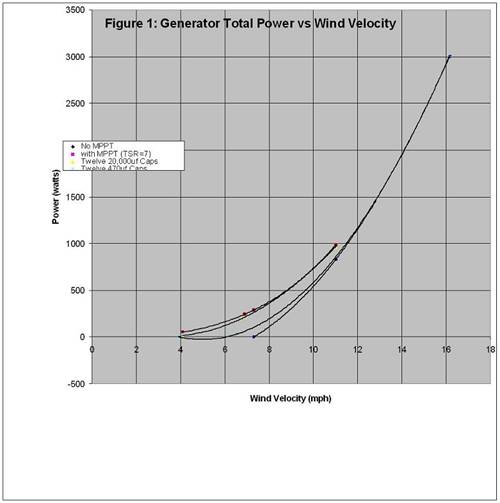
Shown is a plot of total generator power versus wind velocity for the following combinations of circuits:
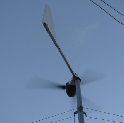
1 Windmill with no MPPT: This is the curve on the lower right. It shows power versus wind speed for my 20� windmill (described in detail here: http://www.fieldlines.com/story/2009/3/2/171331/4786 ) without MPPT. The windmill begins to generate power in wind speeds slightly above 7 mph.
2.Windmill with PWM MPPT: This is the curve on the left and shows generator power versus wind speed for my 20� windmill with the PWM booster circuit. This method holds the TSR near the optimum operating point of TSR=7.0. This is about the best power output that can be expected for this type of windmill.
3.Windmill with Capacitor MPPT: Two curves are shown: one with twelve 20,000uf capacitors; the other with twelve 470uf capacitors. Notice that the curve using 20,000uf capacitors comes close to providing the same power versus wind speed as the PWM circuit. The 470uf circuit provides little boost at wind speeds under 6 mph; above 6 mph it provides about 20 to 30% of the power as the PWM circuit.
Conclusions:
The following conclusions apply to my 20� diameter windmill:
1. The capacitor MPPT circuit is simpler and possibly more reliable, especially if large robust capacitors (20,000uf, 200 volts) are used.
2. The capacitor MPPT does not perform well when using smaller and less expensive capacitors (470uf; 200 volts)
3. The PWM circuit uses more components and is therefore more complicated and possibly less reliable than a capacitor circuit. However, it can be made relatively inexpensively using components from Radio Shack or EBay.
4. A PWM circuit is easy to calibrate to achieve MPPT. It tracks the MPP from low (3mph) up to the wind speed (18mph) where the peak TSR naturally occurs. This circuit is good for windmills designed with a high cut in speed (7mph) like the 20�.
Action:
I looked for the large (10,000 to 30,000uf) 200 volt capacitors on EBay and found a few expensive choices. If I were starting over, I would consider capacitor MPPT if I could find these capacitors for around $5.00 each. Until then, I�m sticking to the PWM approach.
Analyses:
Some of you are probably interested in how I arrived at the power versus wind speed plots in Figure 1. Here is a summary of what I did:
1. Windmill with no MPPT. This calculation was done in two steps, as follows:
a. The basic generator and rectifier circuitry were modeled using TINA II (free software provided by Texas Instruments). A circuit diagram is provided below including instrumentation. Generated voltage and frequency are an input. Generated power (PM2) is an output.
b. Generated power, voltage, and frequency are then input into my wind turbine EXCEL model that includes the fundamental generator parameters, such as:
i. Flux per magnet, number of magnets, air gap
ii. Number of turns per coil, coil resistance, number of coils, number of phases
iii. Resistance of conductors
iv. Rotor radius and coefficient of performance
v. Wind velocity
vi. Battery bank voltage
Output includes rotational speed, voltages, currents, torque, power, coil temperature, and TSR.
An iterative solution is conducted between the above two models until a wind velocity is found where generated power, frequency and voltage agree between the two models. This solution provides the input for the above plot of generated power versus wind velocity. Field tests including watt meter, wind velocity, and oscilloscope readings show that the model provides a good representation of windmill performance.
2. Windmill with MPPT: This calculation was done using basically the same approach as described above, only, the circuit controlling PWM MPPT was added to Figure 2. This is the same circuitry show in the above mentioned thread.
3. Windmill with Capacitor MPPT: Again, the same approach was used as described in 1, above only the following circuit was used to model the capacitor MPPT:
The 0.001 ohm line resistances are included for analytical stability in the TINA II program. The in line capacitors are electrolytic and two are installed with the negetive terminals connected together. This results in a total capacitance = 1/2 the rated and a voltage = 2x rated. Each capacitor shown represents the combination of the two electrolytics.
BobS |
| |
SparWeb

Senior Member

Joined: 17/04/2008
Location: CanadaPosts: 196 |
| Posted: 08:15pm 08 Dec 2009 |
Copy link to clipboard |
Print this post |
|
[feigned annoyance]
 Here I am plugging away at Spice models and I've got capacitors sprawled all over my desk and you come along and steal my thunder! Here I am plugging away at Spice models and I've got capacitors sprawled all over my desk and you come along and steal my thunder!
[back to normal]
Hey Bob, 
As you've guessed, I'm also keenly interested in these "poor man's" MPPT schemes. I am also using computer models and the results that I get are starting to bear some resemblance to reality.
I am eager to test my model with the caps I've assembled, but I have been hampered by a fierce winter storm and dreadful cold. I can't access the base of my tower with the 6-foot deep snow drift around it!!!
I'm fairly convinced already that both devices offer benefits, and we may be down to just the optimizing/parts selection phase for them, too.
One comment - I'm staying away from linking the speed of the wind to the speed of the generator. There's too much depending on the particulars of the blades and even turbulence when you go down that road. Those who come along and read your results will find it easier to relate your conclusions to their case if you don't stir Cp and diameter into the brew. A factor that can replace all of the facts postulated about the generator is to just pick a "volts/RPM" value for the generator. Then for a series of RPM's you can find the AC volts and frequency and let the model run from there. I found this to work simply enough and suits the Spice modelling software. Tina may be different. BTW Spice doesn't clutter up the schematic with dummy resistances like Tina does.
If that's not how you want your model to operate, then forgive my presumption.
In my model, I have higher resistances, lower EMF and lower frequency, and I need larger values of capacitor. This is all because I'm modelling my own generator, which is a motor conversion that delivers up to 400W.
Now that you've provided info for yours (an I assume you optimized the cap value) I'd like to try it in my model and see what happens. Looking back to your Fieldlines posting on your wind turbine, I found an EMF of about 38V / 100RPM - does that sound about right?
I'll be in touch.
Steven T. Fahey |
| |
GWatPE
Senior Member
Joined: 01/09/2006
Location: AustraliaPosts: 2127 |
| Posted: 10:16pm 08 Dec 2009 |
Copy link to clipboard |
Print this post |
|
Hi Bob,
I can only say for the moment that you have confirmed my findings. The cap sizing is linked to the required power handling.
The 470uF caps would be for a much smaller windmill. Check the caps sizing in the cap article.
I have never stated perfect matching, and even your setup will require compensation for changing output loading.
I don't have any simulation software, so cant offer readers any explanation why you have shown negative power output for a cap arrangement model. Possibly the model is not right, as I have only seen positive power gains with my doubler and quadrupler cap arrangements.
The differences are in the order of 10's of watts on my windmill, as I have a voltage doubler and voltage quadrupler on my windmill and it is closer to optimum, as I have achieved better cap matching.
My testing has shown that slight imperfections in cap sizing are compensated by the blades operating slightly to one side of the optimum TSR, but still close to overall optimum output power, within limits of experimental measurement.
The key is the boost, to get output voltage gain that allows current, where before, there would be none.
Gordon.
become more energy aware |
| |
bobshau
Newbie
Joined: 22/11/2009
Location: United StatesPosts: 27 |
| Posted: 10:31pm 08 Dec 2009 |
Copy link to clipboard |
Print this post |
|
Hi Steven,
I look forward to seeing the results of your capacitor booster test and the modeling.
In the mean time, I have a few questions on your statement, as follows:
"I'm staying away from linking the speed of the wind to the speed of the generator. There's too much depending on the particulars of the blades and even turbulence when you go down that road. Those who come along and read your results will find it easier to relate your conclusions to their case if you don't stir Cp and diameter into the brew. A factor that can replace all of the facts postulated about the generator is to just pick a "volts/RPM" value for the generator. Then for a series of RPM's you can find the AC volts and frequency and let the model run from there."
I agree that inputting AC generated volts and corresponding frequency into your spice model will get you power delivered through the Capacitor portion and through the main rectifier portion of the circuit.
My questions are: "How do you relate this calculated power to the corresponding TSR?" How do you decide if the circuit is doing MPPT?
You asked:
"Looking back to your Fieldlines posting on your wind turbine, I found an EMF of about 38V / 100RPM - does that sound about right?"
No, the EMF = 21.8V/100RPM
Looking forward to hearing from you.
Blessings and peace.
Bob
BobS |
| |
bobshau
Newbie
Joined: 22/11/2009
Location: United StatesPosts: 27 |
| Posted: 02:03am 09 Dec 2009 |
Copy link to clipboard |
Print this post |
|
Hi Gordon,
This post responds to some of your above mentioned comments.
You said:
"I have never stated perfect matching,...."
Yes, I learned from my analyses that "perfect" matching using the capacitor circuit is hard to achieve. "Good enough" matching can be achieved for my windmill using large, expensive caps.
You said:
".....and even your setup will require compensation for changing output loading."
Yes, the circuit inherently provides compensation for changing output (and input) loading. That is the beauty of the voltage regulated PWM circuit; it inherently tracks the MMP using Vr as an input providing MPPT with wind speeds between 3 to 18mph.
You said:
"I don't have any simulation software, so cant offer readers any explanation why you have shown negative power output for a cap arrangement model. Possibly the model is not right, as I have only seen positive power gains with my doubler and quadrupler cap arrangements. "
There is no negative power output. The 470uf cap curve was plotted through positive power data points using the EXCEL trendline "3rd order poly" and showed a very slight dip below the axis even though none of the data points were negative. It is right on everywhere else so I didn't worry about it.
You said:
"The differences are in the order of 10's of watts on my windmill, as I have a voltage doubler and voltage quadrupler on my windmill and it is closer to optimum, as I have achieved better cap matching."
Could I see your analyses/data that support the above statement? Also, please send us a schematic of what you are using on your windmill.
You said:
"The key is the boost, to get output voltage gain that allows current, where before, there would be none."
I thought the objective is to load the windmill generator so the blades run at their MPP for a wide range of windspeeds. Merely getting "current, where before, there would be none" is not MPPT.
Gordon, thank you for taking the time to review and comment on this post. I believe there are applications for each concept reviewed herein.
Blessings and peace.
Bob
BobS |
| |
GWatPE
Senior Member
Joined: 01/09/2006
Location: AustraliaPosts: 2127 |
| Posted: 08:17am 09 Dec 2009 |
Copy link to clipboard |
Print this post |
|
Hi Bob,
I have just run a typical full days recorded data, through the spreadsheet. This is from my new mill as described elsewhere, 24 magnet 3phase 3m rotor.
This is just the sorted, raw logged data at 10 sec intervals, RPM V output power, compared with a cubic power curve. I have not removed any of the data, so there are some glitches that have come through as well. too bad.
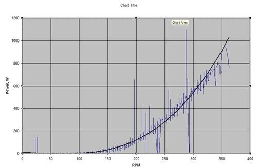
This is the data from my 48V battery system. There is a second parallel setup on the 24V battery, that has the same cubic shape, but is just offset approx 60RPM lower and the power maxes out at approx 50W at about 250RPM.
These are just cap systems, and the 24V battery has 220uF back 2 back, effectively 110uF.
If you want the full setup check the cap article, that Gizmo put up for me.
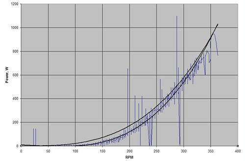
This is a graph of the 48V + 24V total power. The 24V is where I preferentially put low level power. 48V goes directly to the GTI, as I don't have any loading on the 48V battery yet.
this the best I can do at short notice.
Gordon.
become more energy aware |
| |
KarlJ

Guru

Joined: 19/05/2008
Location: AustraliaPosts: 1178 |
| Posted: 11:45am 09 Dec 2009 |
Copy link to clipboard |
Print this post |
|
For most of us plebs, regardless fo the cost of the CAPs the circuit is plain simple and could be called MPPT for dummies as its easy to build,
you dont need any circuit board experience or skills and by the looks of the graph up top the only sacrifice is a couple of hundred watts where the windspeed would barely blow away a piece of paper or lift a windsock and this is on a turbine that potentially makes 3KW at 18mph.
Thus kind of a special case as most of us would be overjoyed to make 500W out of a F&P motor at all.
My 2c, I think the work you guys are doing is great BUT being able to sell one that works on a wide variety of turbines currently on the market and be reliable could change the current "not enough wind here" that plagues us all with this technology.
I do note that Gordon and Phill recommend higher voltage CAPS as they do have a higher ripple current rating and thus may work better.......
There was once a guy who sold large rectifiers on ebay for chinese mills so they would put out decent grunt, I think they were $100 -
if we could offer an MPPT at $150 then all of a sudden you would have a worldwide market and RE users all over the world would be grateful.
Keep up the banter / education, I get a kick out of reading stuff from guys much more educated and in the know than myself.
OZtules takes the cake so far with the article on boiling water in a bucket punching many KW's into a heater element at two metres away from his mill.
---I had tears in my eyes and was day dreaming of being there seeing him running around madly connecting things to try and document it for us to be entertaind by it whilst trying not to electrocute himself.
top work thanks guys
Karl
Luck favours the well prepared |
| |
SparWeb
Senior Member
Joined: 17/04/2008
Location: CanadaPosts: 196 |
| Posted: 08:15pm 09 Dec 2009 |
Copy link to clipboard |
Print this post |
|
Bob,
[quote] "How do you relate this calculated power to the corresponding TSR?" [/quote]
Good question, but it's not one I can tackle very easily without knowing or assuming a lot about the rotor blades. Instead of claiming "MPPT", why not just claim a "boost"? If it works, you can safely say it is increasing the efficiency of the battery charging circuit. To go farther with the claim, then you start bringing in more and more parameters that make the conclusions less useful to other members on the forum.
I did use the term "poor-man's MPPT", but I wasn't very serious. Take apart the acronym, and if you're going to say "Maximum Power Point Tracking", then you'd better have a system that is actively seeking and tracking a maximum power point, either by feeding the computer inputs that it can use to achieve a target or the smarts to respond with a more clever algorithm.
Anyway, I'm still eager to work on this but have no free time to do so. Winter storm has stranded BOTH my truck and my tractor in a field. Fixed the dead battery in one and now the starter is shot in the other. Yeah, I need a "boost" all right...
Steven T. Fahey |
| |
GWatPE
Senior Member
Joined: 01/09/2006
Location: AustraliaPosts: 2127 |
| Posted: 08:50pm 09 Dec 2009 |
Copy link to clipboard |
Print this post |
|
Hi Steven,
As I have said a long time ago, The first part of the process is to get a cubic output from the alternator and convert the alternator from a varying voltage and current to a constant voltage varying current source. Capacitors in a voltage boost arrangement are shown to do this with experiment, and also in theory.
Now that this problem is over, any closed loop Buck MPPT, [probably even one for solar panels] could be used to match the bladeset to the instantanous wind energy with a MPPT function. This would be just a straight DC-DC converter, sized for maximum power handling, with all the protections etc including battery charging and maintenance if required. All that is required on the mill is an overvoltage protection system.
A maximum power seeking algorithm is easier with only one variable to process.
This system would suit applications with a long transmission run into say a 12V battery.
Gordon.
become more energy aware |
| |
bobshau
Newbie
Joined: 22/11/2009
Location: United StatesPosts: 27 |
| Posted: 11:22am 10 Dec 2009 |
Copy link to clipboard |
Print this post |
|
Karl,
Thanks for your input and perspective.
You said:
"....if we could offer an MPPT at $150 then all of a sudden you would have a worldwide market and RE users all over the world would be grateful."
Yes, I would support anyone interested in manufacturing a reliable MPPT supplied to those uncomfortable with making their own.
Blessings and peace.
Bob
BobS |
| |
bobshau
Newbie
Joined: 22/11/2009
Location: United StatesPosts: 27 |
| Posted: 01:54pm 10 Dec 2009 |
Copy link to clipboard |
Print this post |
|
Hi Steven,
Sorry to hear about the tractor and truck. I hope this storm subsides soon. Until then, on the bright side, I suspect your windmill is really putting out the KWH's.
I have a couple of comments on what you wrote above.
You said:
"Instead of claiming "MPPT", why not just claim a "boost"?"
I'm claiming "MPPT" for the PWM circuit because I believe that is what it does. It is not merely providing a "boost". When properly calibrated, it uses Vr as a feedback signal to the voltage controlled pulse width modulator to achieve the maximum power point.
You said:
"To go farther with the claim, then you start bringing in more and more parameters that make the conclusions less useful to other members on the forum."
I don't believe that is accurate. I believe that you and other members can enjoy the benefits of the PWM circuit without understanding all the parameters of the windmill blades and associated performance coeficients. Users will know they are in the ball park of MPPT if their windmill speed doubles under the conditions outlined in calibration procedure.
You said:
"if you're going to say "Maximum Power Point Tracking", then you'd better have a system that is actively seeking and tracking a maximum power point, either by feeding the computer inputs that it can use to achieve a target or the smarts to respond with a more clever algorithm."
I agree. The proposed PWM circuit uses an algorithm. It doesn't have to be too clever because of the almost straight line relationship between Vr and wind velocity. Nature was good to us.
Steven, thank you for taking the time to review and comment on this post. I always look forward to hearing from you.
Blessings and peace.
Bob
BobS |
| |
bobshau
Newbie
Joined: 22/11/2009
Location: United StatesPosts: 27 |
| Posted: 01:57pm 10 Dec 2009 |
Copy link to clipboard |
Print this post |
|
Gordon,
Very interesting plots. Are you saying that you have achieved MPPT because the curves follow a "cubic shape"?
Bob
BobS |
| |
GWatPE
Senior Member
Joined: 01/09/2006
Location: AustraliaPosts: 2127 |
| Posted: 09:25am 14 Dec 2009 |
Copy link to clipboard |
Print this post |
|
Hi Bob,
The capacitors are not a MPPT, but on my windmill allow the alternator to produce close to optimum loading.
What curve would you consider a windmill output power loading should follow to windspeed?
Gordon.
become more energy aware |
| |
SparWeb
Senior Member
Joined: 17/04/2008
Location: CanadaPosts: 196 |
| Posted: 09:28pm 14 Dec 2009 |
Copy link to clipboard |
Print this post |
|
Well, no opportunities arose to hook up my capacitor circuits to the 'mill this weekend. Temperatures down below -20C and this morning we woke up to a fresh -38C. Not the kind of weather to spend standing under a windmill tower watching a multimeter! Even the multimeter will pack it in at these temps!
Anyhow, I did spend some time trying the circuits in Spice, using various combinations of V(open-circuit), winding resistance, and capacitance to find the potential boost in these circuits. All of my models are centered around a 2-pole generator, and I think this is my downfall. I was not able to find any connection or capacitor value that would offer more than the slightest gain in low wind speeds, and often found penalties at higher wind speeds. I'm disappointed with the computer's results, however I still have my kit ready to hook up - hopefully I'll be able to prove myself wrong in the coming week. Armed with my datalogger I hope to have some "with" cap boost data to compare to data I've already got for "without".
With the Spice models, I watched several things going on. Firstly, I was getting very MESSY current waveforms when I selected capacitor values that were turning the boost circuit diodes on just before the main bridge diodes. Spikes of many amps at the f*12 ripple frequency. This phenomenon would go away at higher or lower RPM's, however they became stronger when using capacitor values that were "too large". I could point to an "optimum" between 1mF and 10mF. Any more than that and the boost circuit would always "clamp" the current to 60% of the "unboosted" current. Mysterious.
When using an array of 1mF capacitors in my circuit I could realize a fraction of an amp at wind speeds 1/2 of the un-boosted cut-in. My belief, for the time being, is that the frequency rules the amount of benefit that can be gained. Higher benefits accrue to those whose generators have a higher number of poles.
Steven T. Fahey |
| |
bobshau
Newbie
Joined: 22/11/2009
Location: United StatesPosts: 27 |
| Posted: 02:08am 15 Dec 2009 |
Copy link to clipboard |
Print this post |
|
Hi Gordon,
Good to hear from you.
You asked:
"What curve would you consider a windmill output power loading should follow to windspeed?"
Windmill power will be proportional to the cube of the windspeed ignoring any changes in parameters such as circuit resistances as coils heat, TSR, counter EMF, furling, gusting, rotor inertia, battery voltage, etc. A near cubic relationship can be achieved at a constant TSR not necessairly the MPP TSR.
My problem has been getting good readings in a steady wind. There is always so much variation in the wind (gusting) that I can easily fit a cubic relationship to the data because of it's scatter. (I want a 25' diameter windtunnel for Xmas.)
The best way that I have found to establish if the windmill is at the MPP TSR is to turn off the MPPT Booster and see if rotor speed (Vr) doubles. This is a relatively easy test for the PWM circuit and, in fact, is used to calibrate it. Once calibrated, it is helpful to compare plots of Vr vs. windspeed with and without MPPT up to cut-in.
The same kind of test can be used on the Cap circuit by measuring rpm instead of Vr. It will also require a 3 pole switch to disconnect the caps.
Gordon, I hope I've answered your question.
Blessings and peace.
Bob
BobS |
| |
GWatPE
Senior Member
Joined: 01/09/2006
Location: AustraliaPosts: 2127 |
| Posted: 05:41am 15 Dec 2009 |
Copy link to clipboard |
Print this post |
|
Hi Bob,
The cubic relationship is attained when all conditions are optimum.
Looking at your data for your windmill, the boost cct gives good matching at the lower power levels.
The data shows a cubic relationship at low levels and this reduces to about a 2.5power at the higher levels. I suspect that the tsr is reducing slighly at the high power levels, or there may be furling affecting the output.
I suspect that your windmill is heavily restrained as the 20' rotor would be capable of well over 10kW. Your data maxes out at 2kW.
The "Quixote" graph you provided shows that you can be a fair bit OFF optimum tsr, yet still be pretty good. This probably accounts for why a lot of home grown setups still work OK.
I have found that best results are obtained from an electronic boost and cap boost when the windmill is slightly underloaded.
As far as which setup is better, a lot will depend on the individual builders skills and to some extent local conditions. I have both setups and up to 1kW system, caps would be my choice.
I do suspect that the alternators that we are using have a lot to do with the results [high efficiency and ironless design]. I can say one thing with caps. On my mill, caps perform multiple functions. That being voltage boost for low wind conditions and load reduction in high winds. Without caps my AxFx mill would not produce much useful power. I have saved myself building a new stator for the moment.
An electronic solution will suit mass production, in conjunction with a buck second stage. I was working on this a few years ago now. I did not persue it as the digital system was not better than my analogue one. I wasa looking for a simpler solution
I can see Outback and other producers looking at a boost cct that works in conjunction with std rectifiers and overvoltage systems as an addon to a solar MPPT into batteries or GTI for windmill applications.
I think that the "Skystream" windmill with GTI built in uses this boost arrangement already.
Most DIY is small scale. Your windmill may still be DIY but is 10x more powerful than most F&P type windmills.
I hope many readers take up your offer to supply yours.
I have stated many times that a windmill should produce optimum power whenever it spins [within pysical limits]. Any way to do this that fits in with a DIY builders skills should be encouraged. We have 2 extremes that should cover most DIY'ers.
Gordon.
become more energy aware |
| |
