
|
|
Forum Index : Windmills : first mill. a dual
| Author | Message | ||||
gpalterpower Senior Member Joined: 19/07/2009 Location: AustraliaPosts: 177 |
Well I started making this.. my first mill about 6 months ago, its been a slow process having had a few holdups along the way... mainly family and work! . Originally I was it was only going to be a single f&p , but after viewing projects from other members it seemed to make more sense to go for the dual. I was trying to pick out the best ideas from the forun with a few of my own chucked in . I first started by cutting the shaft and bearings from a f&p and machining the nylon casing into a cylindrical shape 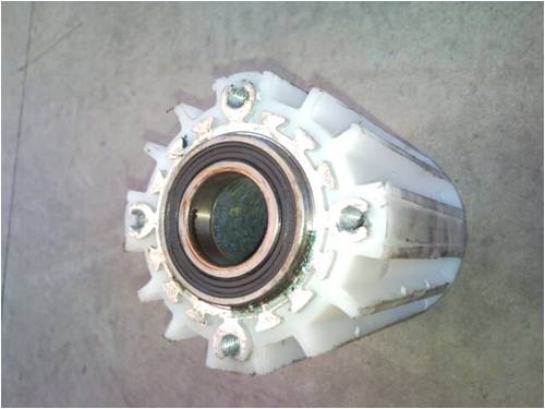
I then machined an old starter motor body(just the right size) and snuggly press fitted the bearing housing into it. 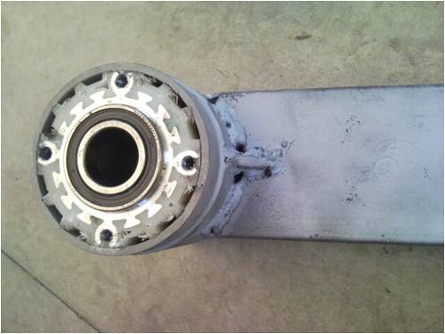
for testing purposes I added a pulley and mounted it into my test bench at work, just to see how much output i could get out of a dual setup. . they are both star wound 2x7c 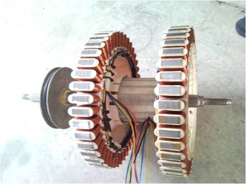
I also connected all of the 7 star points together for a slight increase in output and fed them in to an additional rectifier. 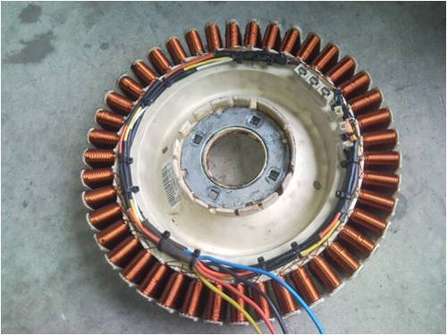
have seen this idea work on motor vehicles for the last 10 years or so with and increase output of approx 10%. so i thought id give it a go 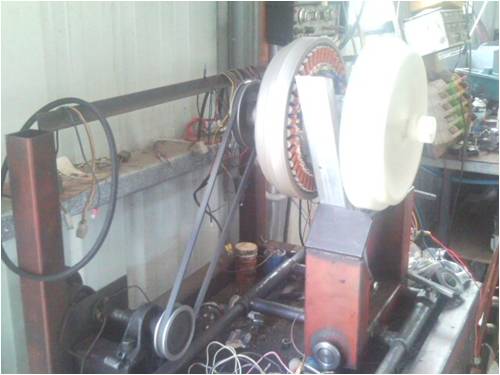
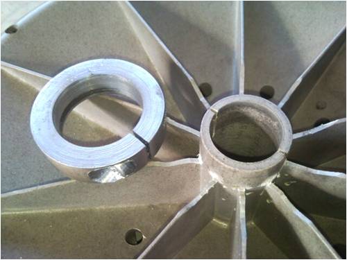
Connected 4 12v car batteries in line and got a readout of 13 amps @65 volts = 845W. I...was...happy. It had more to offer but the belts were slipping on my test bench, but would have been interseting to see just how much it can actually put out. Next was to mount the two stators on to the shaft.the first one (back side) in the usual manner ....just screw it on!! .The front rotor I machined so it snuggly fitted onto the shaft. similar to Phills dual setup. I then cut away some of the webbing 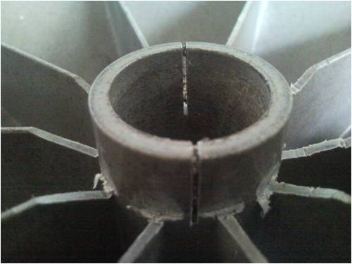
and fitted a ring with a tightening screw to further help hold the rotor onto the shaft. 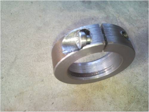
cut the spline of the other end , tapped a 12mm hole and keyed the shaft to fit into my hub 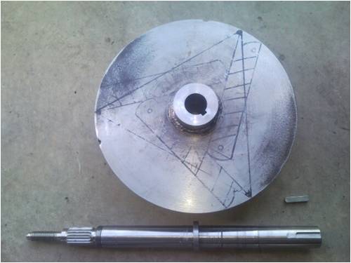
Then tapered the ends of the 22mm dia, 680 mm long solid bar as suggested. The other end I machined a groove for the ubolt to locate to prevent the blade from coming adrift. Drilled 4 holes for plug welding into the 25 mm, 1500mm long od tube, the last hole being 100mm from the end of the solid bar. . 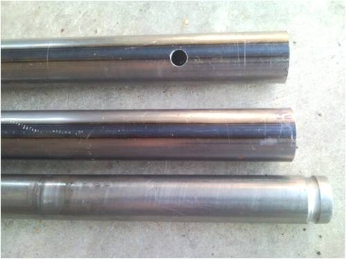
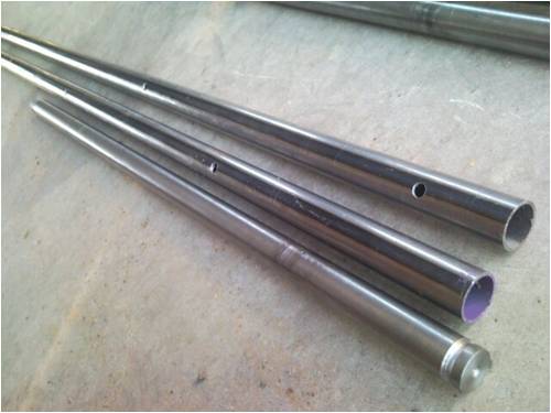
Inserted the round bar into the exhaust tube and mounted all 3 on to the hub, each with two 8 mm u bolts 
This being my first mill, there probably are flaws in my design, so any suggestions of improvements would more than be welcome. more to come! Marcus if it aint broke dont fix it!! |
||||
KarlJ Guru Joined: 19/05/2008 Location: AustraliaPosts: 1178 |
Looks great to me bro, well done dont quite understand how the joining of the star points will work, schematic perhaps? Karl Luck favours the well prepared |
||||
| JimBo911 Senior Member Joined: 26/03/2009 Location: United StatesPosts: 262 |
Nice work there Marcus I have always had reservations about using an F&P shaft for mounting all three (whirring ) blades, not enough steel. I like the way the iron bars extent passed the shaft center line this will add strength and rigidity to your hub plate. Grooving the bars at the rear (instead of the front like I did)is a real plus. NICE Jim |
||||
| Gizmo Admin Group Joined: 05/06/2004 Location: AustraliaPosts: 5187 |
This is a very impressive build Marcus. Lots of good idea's. I've seen the rectifier hanging off the star centerpoint in car alternators before, but never thought of using it on a F&P. A mate works as a autoelectricial and says the same as you, its been around for about 10 years and gives a 10% increase in power capacity. I like the hub and blade mounts too, very solid. Top job, cant wait to see it flying. Glenn The best time to plant a tree was twenty years ago, the second best time is right now. JAQ |
||||
| gpalterpower Senior Member Joined: 19/07/2009 Location: AustraliaPosts: 177 |
Thanks for your comments guys Karl, Im not too sure how joining the star point together works either, but i know from experience it does. Im an auto sparkie for the last 30 years (thats too long)and this concept has been in conventional car altenators for about 10 years or so. take your average vt commodore . bosch brought out 2 alternators for this model, one 90 and 100 AMP . the only difference is a 6 diode plate for the 90 and an 8 diode plate for the 100A , in which the star is connected to the additional 2 diodes.hope this helps. also i quoted i was using 2x7c where in fact it was 7x2c my nistake 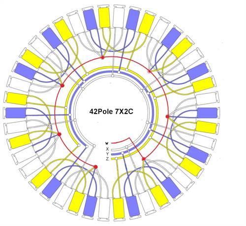
Jimbo, I understand what you mean about the shaft, but there are a few duals out there flying. time will tell, but i'll definately keep my eye on it with routine maintence when she's up!! Glenn, Would you think its necessary to add caps to the star circuits as well as the 3 phases, and if so would you keep the same values? marcus if it aint broke dont fix it!! |
||||
| Tinker Guru Joined: 07/11/2007 Location: AustraliaPosts: 1904 |
Would you have a diagram to show how the 2 extra diodes are connected? I'm curious and would like to 'borrow' that idea. Klaus |
||||
| GWatPE Senior Member Joined: 01/09/2006 Location: AustraliaPosts: 2127 |
Hi Tinker, The centre connection of the series diodes connects the star point to the + & - battery rails. Looks on paper like just an extra half bridge. I imagine that at higher power levels, the star point voltage has an AC component that is clamped by the diodes, with resulting extra current to the loading. This probably works best with the highly nonlinear loading that is a battery and rectifiers. Gordon. become more energy aware |
||||
oztules Guru Joined: 26/07/2007 Location: AustraliaPosts: 1686 |
Klaus, Marcus, I think Gordon is on the right track with this. The diodes seem to be there to pick up the pieces from the poor loading that battery charging does to the waveform. Some call it crest factor, others power factor. Either name refers to using only the tops of the waveform... ie when Vin is greater than batt voltage, the diodes conduct, which leaves a fair proportion of the waveform unused (the bottom parts less than batt voltage) This basically turns the sine wave into a squarish wave... the top will be flat (batt voltage). This produces harmonics (in fact a good deal of high frequency noise) This is usually lost to us..... but if you put a few diodes as you have suggested, it allows you to pick up the high frequency noise and convert it to useful output. Note.... you will need a high voltage, ultra high frequency diode I suspect.... perhaps as high as 600v@3A.... depending on the wiring scheme in the stator...( but 200v as a minimum I would guess) It can see the high frequency noise/voltage > batt voltage in the any of the phase coils and directs that to the batteries.... where the slow diodes would not. At least, that's how i think it works  ... any counter comment welcome. ... any counter comment welcome.
Village idiot...or... just another hack out of his depth |
||||
| KarlJ Guru Joined: 19/05/2008 Location: AustraliaPosts: 1178 |
we've seen this before, someone called it an "open delta" arrangement. Perhaps we should call this open star? http://www.thebackshed.com/windmill/forum1/forum_posts.asp?T ID=558&KW=open+delta 'tules would the "normal" square type rectifiers do the job, I dont understand why the frequency here would be any different than the other 3 phases. when one of the admin guys is around perhapos they could add this to the F&P rewire page.... Phill this might get you over the hump that is 750W for the f&p dual, turn it into a 825W machine! I'm thinking putting CAPS on this end would be a looser as you would be doing it to both ends.... More testing for those with mills and doublers! Karl Luck favours the well prepared |
||||
| readyakira Senior Member Joined: 17/07/2008 Location: United StatesPosts: 114 |
I would suspect that the reason for high freq is that you are seeing all three phases thru one wire? which means 3 times the frequency? Don't you think Free/Renewable energy should be mandatory in new buildings? |
||||
| oztules Guru Joined: 26/07/2007 Location: AustraliaPosts: 1686 |
[quote]'tules would the "normal" square type rectifiers do the job, I dont understand why the frequency here would be any different than the other 3 phases. [/quote] No. Those diodes are for low frequency switching. Their reverse recovery times are far too slow to pick up the extraneous high frequency noise that we want to convert. When the diodes switch on, they are non-linear devices. They have rise times where the P-N junction effectively turns on. It is in this region of time where a lot of noise and harmonics get generated. They are neither on or off for a period... the flat part of the wave is filled with harmonics too, but is clamped by the battery.. but I think can be induced into the non-conducting coils at the same time... not sure about this bit. The primary frequency of the generator is not relevant really to the discussion as it is so low as not to matter... ie seeing all phases through one wire will not result in high frequencies. In battery charging in particular, this noise saps a lot of energy, as we are switching on a very low impedance (short circuit/battery) load, so instantaneous currents can be high, as can the associated voltage spikes. Normally this noise just circulates and dissipates...but As the spikes and the frequency will get very high and fast, we need ultra high speed diodes to catch these spikes... and bank the power instead of losing it to heat. Hmmm, consider this, if you hit a hammer on a sheet of steel, the primary frequency of the work is a single pulse.... the real work done will be to deform/bend the steel, but the side effect/(losses not used to bend the steel).... will be a huge multiple of frequencies and associated harmonics that rattle your ears... some very high..... yet the single pulse was a very slow frequency... this is energy sapping noise ..............oztules Village idiot...or... just another hack out of his depth |
||||
| GWatPE Senior Member Joined: 01/09/2006 Location: AustraliaPosts: 2127 |
Hi Oztules, my understanding is that this arrangement converts the normal star winding outputs at low power levels to an automatic star/delta output as the currents increase and the star point has AC superimposed on it as the other ends are clamped by the diodes to the battery. At maximum power the arrangement is really just the same as independent rectification of the phases with one diode half bridge conducting for 3 phases, so I see a frequency ripple of 3x fundamental. The switching edges will have a higher frequency edge component, so high speed diodes would be the go. The frequency aspect may need to be confirmed by testing. Gordon. become more energy aware |
||||
| oztules Guru Joined: 26/07/2007 Location: AustraliaPosts: 1686 |
Thanks Gordon, this was my initial reaction when I drew it out. It was later when I found some circuits that I wondered. The circuits I have seen use 35A shottky for the main and 200v ultra's for the other two... but only 3-5A... so I did not conclude that they were hunting for amps from the delta config. I figured they would not use ultra fast 100khz diodes for the frequency of the alt, and would have figured on high current diodes if looking at the delta winding......they seemed to be looking for noise But I'm certainly open to suggestions. ............oztules Village idiot...or... just another hack out of his depth |
||||
| GWatPE Senior Member Joined: 01/09/2006 Location: AustraliaPosts: 2127 |
Hi Oztules, The fact that only an approximate 10% increase in power is attained means low current diodes need only be required. I do not have a setup to test this at the moment. I will speculate here: I only think that lower efficiency alternators will benefit from this arrangement anyway. The diode function seems to rely on shunting excess coil emf, and this needs to be approx 2x the normal output emf. This is also working against the other 2 phases. There could also be some factor with reducing regulator glitches. I think that there are better options to increasing power output. Gordon. become more energy aware |
||||
| Barry T Coles Senior Member Joined: 30/07/2009 Location: AustraliaPosts: 109 |
Hi Marcus Excuse my ignorance with power generation, 3 phase grid, single phase grid & DC I understand. Can I assume from your picture that the red wire W is the neutral & the others XYZ are the phases as in 3 phase grid? Regards Barry I need to learn from the mistakes of others. I dont have the time to make them all myself. |
||||
| KarlJ Guru Joined: 19/05/2008 Location: AustraliaPosts: 1178 |
I think you're right Barry, the red wire is the centre point of the star which would be the neutral. Hence I was at a loss as to how you would get any power from the neutral point. I put it in to the too hard basket as I'm running (2x) 15A extension leads down the mill, and dont have any spare wires, nor do I hop to understand what this might do to the cap setup. He can hunt for the extra 10% and i'll get the other 50% from the expensive CAP solution 
takes all kinds Luck favours the well prepared |
||||
| gpalterpower Senior Member Joined: 19/07/2009 Location: AustraliaPosts: 177 |
Hey Barry, Im probably a bit ignorant when it comes to 3 and single phase grid stuff. not my forte. Im strictly 12 an 24v ! So....im not too sure if it would be called a neutral as it is all above ground. Just thought I would try the idea on the f&p that is used on motor vehicles, which seems to work quite well for attaining additional output. To tell you the truth I didnt think it would work. Thought it might just short it out until I put it in my test bench and ran it up. There are no special or different diodes for the star connection. All the 4 main pos diodes are the same and all for the the neg's too. As for the noise factor, only a small cap(22uF) on the outside of the alternator is required, without it you can hear the whistle thru the radio. .........Marcus if it aint broke dont fix it!! |
||||
| Barry T Coles Senior Member Joined: 30/07/2009 Location: AustraliaPosts: 109 |
Thanks Marcus & Karl This one interests me but before I go and rewire what ammount of torque is required to make it rotate ie will it turn reasonably easy by hand or is the power needed to great for that. Cheers Barry I need to learn from the mistakes of others. I dont have the time to make them all myself. |
||||
| gpalterpower Senior Member Joined: 19/07/2009 Location: AustraliaPosts: 177 |
Barry, Before I ran my f&p in the bench, I tried turning it by hand. Felt much the same with and without the stars connected , so maybe not much more torque is required to set it spining. I will do some more testing this time with caps in the bench, (time permitting at the moment...really busy at work) firstly just 3 phase and then with joined stars. Lucky this isnt some job a customer is waiting on. They would have given up!! I also find this an interesting subject, but dont really know if it is going to be a good thing or not. This really is new territory for me. Time, testing and ...perseverence will tell ......Marcus if it aint broke dont fix it!! |
||||
| Barry T Coles Senior Member Joined: 30/07/2009 Location: AustraliaPosts: 109 |
Thanks Marcus I've got five F&P's so I'll wire one up given time & see how it goes. Cheers Barry I need to learn from the mistakes of others. I dont have the time to make them all myself. |
||||
| The Back Shed's forum code is written, and hosted, in Australia. | © JAQ Software 2026 |
