
|
|
Forum Index : Windmills : ALUMINIUM BLADES UP - NEW HUB & TUBES
| Author | Message | ||||
fillm Guru Joined: 10/02/2007 Location: AustraliaPosts: 730 |
Hi All, It has taken a while but I think well worth the effort , I have decided to split all this into two posts as there would be too many photos . Here I will mainly deal with my new blade spigot/mount design . The other post deals mainly with the strength of the blade materials and my obersavations from what I have seen in real terms with regards to " How Much Force Are We Dealing With ". 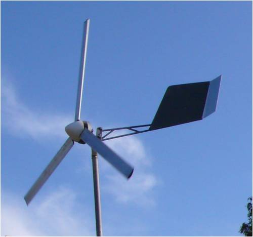
I'll start at the end and work back through all the individual steps and tests I went through to get the first set of Aluminium blades up and flying , I also took on board a lot of what was said in the "New Aluminium Blades" thread and hopefully have addressed a lot of what was worked out there and with what I have learned and observed from the failure of the 3.2mtr pvc set , I now feel confident that I have a set of 3.2mtr blades on the Ax Fx that will stand up to high wind conditions ,forces generated in rapid shut downs, forces generated by yawing & furling and centrifugal forces , but only the test of time will tell . Finished , a stand does come in handy as do sunglasses with these out in the sun . 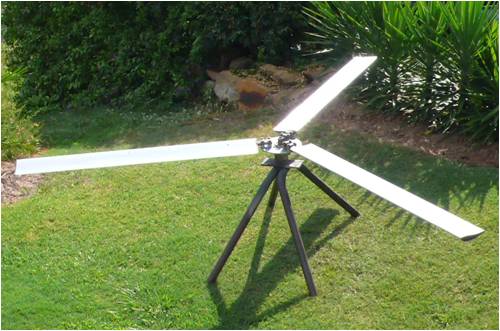
Blade Hub showing the mounts , I set myself quite a few design requirements. 1- MUST BE STRONG 2- MUST SHARE LOAD OVER 3 POINTS AND EACH POINT ABLE TO CARRY THE EXPECTED FULL LOAD 3- ABSOLUTLY NO WELDING IN STRESS AREAS 4- MUST BE ADJUSTABLE IN ALL DIRECTIONS TO GET PERFECTLY SMOOTH RUNNING ( TIP TO TIP , RUN-OUT , BLADE ANGLE ) 5- MUST BE EASILY ASSEMBLED , REMOVED AND ABLE TO BE REASSEMBLED IN EXACTLY THE SAME POSITION 6- CAN BE ADAPTED TO OTHER TYPES OF BLADES IN THE FUTURE 7- CAN BE EASILY RETRO FITTED TO ALL FLAT PLATE TYPE BLADE HUBS 8- KEEP THE COST TO A MINIUM 9- KEEP IT SIMPLE AS IT CAN BE Blade tube mounts and hub , lower outer clamp block is tack welded on the outer face once tip to tip measurement was within 3mm , the inner lower block has a 3mm roll pin to keep it aligned and also allow it to be lifted for shiming to get perfect tip run-out . Not having correct tip to tip will cause an imbalance due to differing lift/pressure loading when the airfoil is working , it might not seem much but I chased a out of balance problem for a week and it came down to one blade being 1deg different causing differing lift at a certain rpm which wobbled the top of the tower. 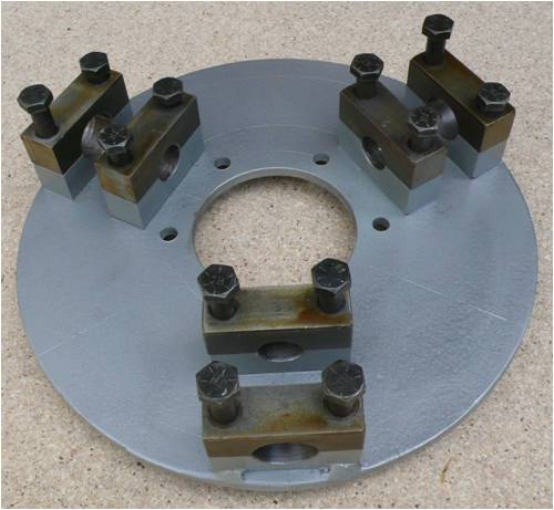
Shows shim under inner mount to set tip runout , .25mm gave approx 5mm at tip 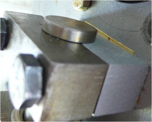
Setting tip run out , having a set up pole and being able to rotate the blades does make it easier, I have found that if the tips are not running true ( within 5mm ) it is as bad as being out of balance and causes extra stress on the the whole structure , I was able to set these to 2mm . 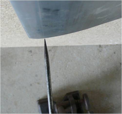
Setting blade angle , as I said above when I chased the out of balance and it came down to a blade being set at a different angle of attack by 1deg , well I did it again when I put these up , I thought I had everything perfect and when they took their maiden first run the tower started wobbleing at a certain rpm , I had set them with a pendulum protractor and probably rushed through this step a bit , so not leaving anything to sight error I taped a small cheap laser pointer to a steel rule and set the attack angles exactly , each blade must have the trailing edge in the same position . 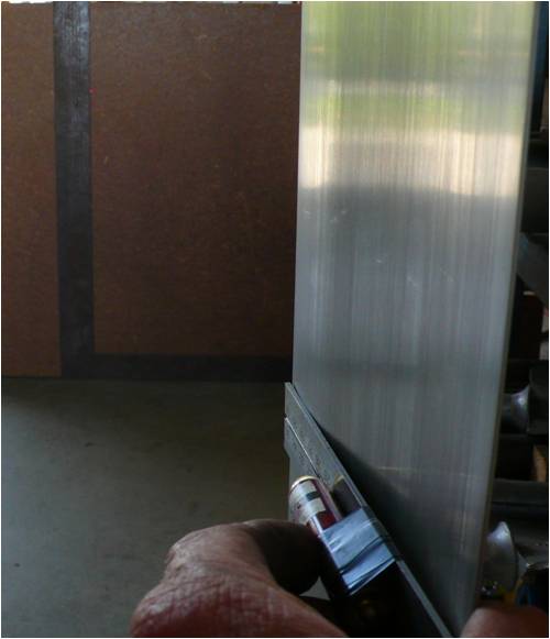
Getting correct balance , This was easy once everything else was correct , I used 2.5mm wire inserted into the u channels that are used to now screw the end caps on . It is best to have the blade angle set almost correct before doing the tip run out as it can effect this area if the blades are not perfectly straight. 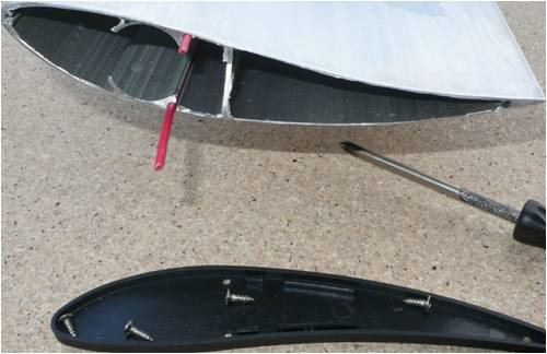
The next set of pics show the blade tube assy and clamps , the clamps are machined out of 20 x 40 - 1020 machined bar and use 4 x 3/8" high tensile bolts , the solid is 22mm 4140 machined bar and has the section cut in to lock into the inner clamp , the 25.4mm s/s tube has a 90deg flare that butts up against the outer clamp block and then the 6mm hole @ 80% of the solid to lock the blade , tube and solid as one . Each section has been load tested and the loads and testing info is next . 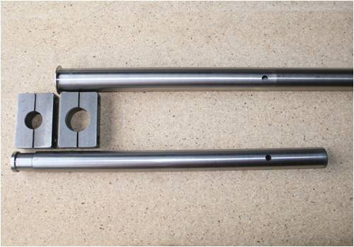
Shows solid in tube and sitting in clamps , the clamps can be moved further apart for bigger blade hubs and blades . 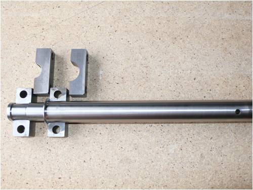
Shows roll pin under the inner mount to allows assy to piviot to align the tip to tip measurement , outer holes can be elongated with a round file if needed to get correct measurements before tac welding outer block in position. 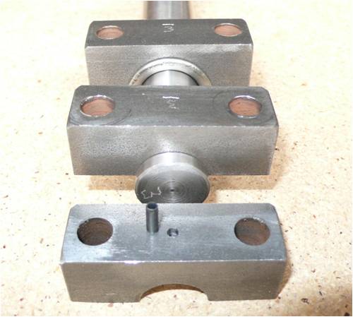
Next is the load tests in my press , first was to mount a clamp assy to a 6mm x 75mm angle , 6mm is the minium I would use for a 250mm blade hub . 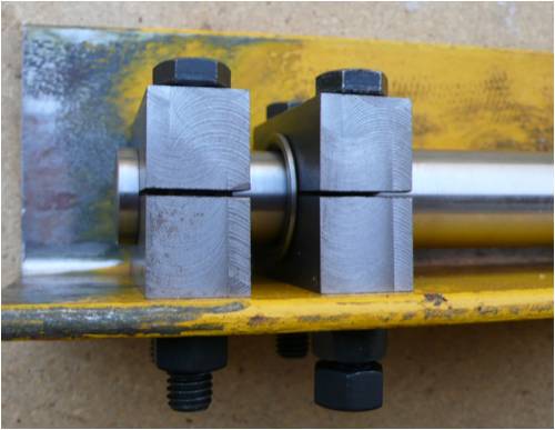
The 4140 x 22mm solid shown here has been taken up to ( 6.5 ton ), no damage was evedient to the bolts , the load face of the block was slightly raised from the bolts being compressed into it. 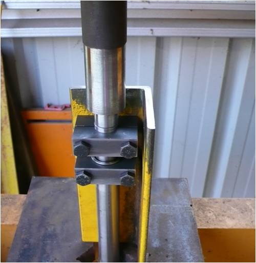
The rear clamp removed and one of the older crimp clamps on the end of the s/s tube to stop the solid pushing through , this was taken up to ( 4 Ton ) with no sign of movement or damage to the flare , it takes up to 6 Ton to do the flare . 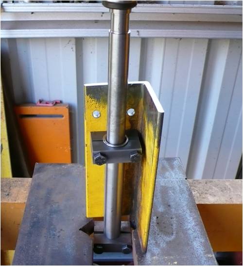
From tests I did with a previous design I already know that the yeild strength of a 1/4" bolt through the s/s tube is arround 2 Ton , so with all these tests I feel I have all my bases covered out to the 1/4" bolt , from there out it goes to the strength of the blade material and how it is attached , all those tests are in " Testing Blade Strengths & Forces " PhillM ...Oz Wind Engineering..Wind Turbine Kits 500W - 5000W ~ F&P Dual Kits ~ GOE222Blades- Voltage Control Parts ------- Tower kits |
||||
SparWeb Senior Member Joined: 17/04/2008 Location: CanadaPosts: 196 |
All I can say Phill, is that I'm impressed! You've gone to an awful lot of trouble to ensure your safety and the effort shows in the tests, and in how good it looks. Steven T. Fahey |
||||
| HeadsUp Regular Member Joined: 06/12/2009 Location: AustraliaPosts: 43 |
did you do a load test on the assembly under tension ? would have been nice to anchor the end in both clamps and apply force pushing the blade end away to see what the yield point was but of course that doesnt take resonant or cyclical fatigue into account , or thermal cycling but its good to have raw numbers to compare against theoretical calculations best wishes edited . PS where is the cheapest place to buy 3 metre lengths of Ali blade ? , i am tempted to make a 6.3 metre ( diameter ) set , but the price i saw somewhere here looks like it is retail plus plus |
||||
Bolty Regular Member Joined: 03/04/2008 Location: AustraliaPosts: 81 |
Hi Headsup! Maybe I am mis-interpreting what your intent is in asking about 3 metre lengths of Ali blade. If you are thinking about making a 6.3 metre set I would very carefully reconsider the size. Centripetal acceleration forces required to hold a large blade set of this size needs to be carefully calculated at your intended maximum rpm. Otherwise the "Centrifugal" forces will stretch your mounting beyond the limit. I speak with some experience about a similar configuration with the previous extruded PVC blades. I did not consider the strength of the mounting adequately when I built a 5 m rotor with 2.4 m radius blades. I was using 25mm steel tubing with a wall thickness of 3mm (after the solid section). The "centrifugal" forces were so strong that the 25 mm tubing was stretched apart to breaking. From memory this force was calculated to be about 6 tonnes at 600 rpm. Since the breaking force of the tubing was around 5 tonnes (again from memory), it is clear to see that the mounting area of extruded blades, (using a 25 mm round section) is simply not enough for blades of this size. I suspect that Phil's PVC blade failure was very similar even though his diameter was only 3m. My blades ended their life very quickly. The first blade to release, flew 100 metres away. Luckily I live on a large block, and no damage was caused to any property or people. Whilst they were spinning, it was amazing how much power they produced. They were also incredibly quiet and seemed to have very little drag! Since Phil (and many other contributing forum members) have done a lot of calculations on the various loadings, I would carefully adopt Phil's recommendation on what is considered to be the safe maximum diameter for these Ali blades. The quest for more power through larger areas is a worthy goal, but it needs to be done safely! |
||||
| Gizmo Admin Group Joined: 05/06/2004 Location: AustraliaPosts: 5187 |
I think you could get away with a 6m turbine if you used shorter blades mounted on stronger extensions. If the blades were 2m long, and they were mounted 1m from center, then the loading forces at the blade center would be reduced. The RPM will be down anyway, larger diameter means less RPM, more power. You would loose some swept area in the center of the turbine, but not a lot. A 6m turbine has a swept area of 28m2, take away the 1m extensions ( 3.14m2 ), leaves you with a 24.8m2 swept area, or about 10% loss in area. By loosing 33% of the inner blade, you only loose 10% or swept area, but gain a lot of strength. The inner part of a turbine is the most stressed, and in return gives the least power. On bigger turbines it would make more sense to use this area for strengthening the turbine structure, and mount the blades further out. However, blades mounted out from the center dont look as pretty. Glenn The best time to plant a tree was twenty years ago, the second best time is right now. JAQ |
||||
| Gizmo Admin Group Joined: 05/06/2004 Location: AustraliaPosts: 5187 |
I should add, though, that a 6 meter turbine is really beyond the scope of this forum. There are a whole lot of other engineering challenges with such a large machine. Glenn The best time to plant a tree was twenty years ago, the second best time is right now. JAQ |
||||
| HeadsUp Regular Member Joined: 06/12/2009 Location: AustraliaPosts: 43 |
i wouldnt be approaching a 6 metre unit without good structural analysis 2 metre blades mounted 1 metre out might still give good torque , but the bare pipe wont be great for drag losses. ideally it would be nicer to have optimum blade twist but the structural element ( 25 mm tube ) has enough limitations on it with even the standard extrusion . If a 5 metre blade set failed early using 25 mm OD x 3 mm wall tubing , that just confirms the risk to any DIY without an engineering background , i would want to be designing for a 10 -20 year life at least. i have considered an option ( back of envelope ) , of using two tubes inside the blade , one round , one crushed in rollers to match the shape adjacent to the vertical web inside the blade pity the people who made these extrusions couldnt make one to suit 32 -36 mm tube , 3 metre lengths , 160 - 200 mm wide |
||||
| HeadsUp Regular Member Joined: 06/12/2009 Location: AustraliaPosts: 43 |
I had a closer look at the photos again fillm do you really feel you still need the bolt hole through that tube with the flared end and clamping force of the half clamps used ? if you say the flare is good for 4 - 6 tonne without deformation then wont that be enough ? and if you really felt you wanted the bolt hole too , then could you move it further away from the end of the 4140 round bar , that hole stands out a bit to me as a stress node origin . ( i work in structural , hydraulic , pneumatic and power transmission design and manufacturing ) |
||||
| fillm Guru Joined: 10/02/2007 Location: AustraliaPosts: 730 |
Headsup The 1/4" bolt is at 80% of the length of the 4140 , I am sure it says that somewhere , to me that is far enough away from the two main load points not to be of concern , it also locks the blade , s/s tube & solid as one , I tried to incorperate as many shared load points as possible and each able carry the the anticipated max load and then some . I tested the solid to 6t & the tube flare to 4t , I am not reliant on the clamping force to hold load but to keep the clamps in position and transfere their load to the 3/8" bolts when needed . Obviously the tests I did are not every load that can be exerted but if you would like to do more comprehensive testing and design and build a more suitable mounting as I am sure you would be very capable off , working in (structual ,hydraulic , pneumatic and power transmission design and manufacturing) , I will send you a sample piece to do these tests . The blade profile has been manufactured more for 2m to 3m & may be max 3.5 m wind mills , 6m dia would be very much a specialist field and as Glenn mentioned at that size it is getting way beyond the scope of this forum . PhillM ...Oz Wind Engineering..Wind Turbine Kits 500W - 5000W ~ F&P Dual Kits ~ GOE222Blades- Voltage Control Parts ------- Tower kits |
||||
KarlJ Guru Joined: 19/05/2008 Location: AustraliaPosts: 1178 |
Now that I have a set, (in fact the set shown above) dont mind If I comment. a 6m set of blades would be fine as long as you didnt try to run them to 500+rpm, Im thinking 150rpm would have similar if not less stress on the tube than the 1000rpm 3m blade set that the maths was done on. Obviously you would need the right motor as any number of F&P's isn't going to cut the mustard here! by my rough calcs a 5m set should be safe to 300rpm which is confirmed by the broken set at 600rpm. again anything will break given the forces, the 3m set will also break if you abuse them. Luck favours the well prepared |
||||
| Bolty Regular Member Joined: 03/04/2008 Location: AustraliaPosts: 81 |
It is fine if you limit the rpm to 150 rpm for 5m blades. How would you go about limiting the rpm to this figure? My chinese alternator had no hope of stopping the enormous power that was generated, despite the stator being shorted. I think due to the large value of angular momentum of the blades, furling was ineffective. |
||||
| KarlJ Guru Joined: 19/05/2008 Location: AustraliaPosts: 1178 |
How much was the mill offset to the tower? I'd imagine not much. What size was the chinese mill, perhaps simply not big enough, if you have no means to extract any power, ie the worst case scenario, I cant see any reason why with a decent furling setup that it wouldnt work. Luck favours the well prepared |
||||
| KarlJ Guru Joined: 19/05/2008 Location: AustraliaPosts: 1178 |
BTW 5m should be good for 5KW. Perhaps the AXFX 400 will be good for this, i'd imagine its going to be a tough balance between low RPM and enough turns and heavy enough wire. Perhaps Phill and Gordon can let us in on what size the 400 will be suitable for and the expected outputs.... I read a post of fieldlines suggesting 10mm offset for every 1' of blade thus 100mm for a 10' turbine thus a 5m set of blades would be looking at least an offset of 165mm. now none of the chinese mills have anything like that as far as I can see, thus keeping the rpm down is going to be really tough Luck favours the well prepared |
||||
| The Back Shed's forum code is written, and hosted, in Australia. | © JAQ Software 2026 |
