
|
|
Forum Index : Windmills : Failed Experiment...
| Author | Message | ||||
| dvn8 Newbie Joined: 04/01/2010 Location: Posts: 10 |
I have spent the last 3 weeks in my spare time decogging a F & P smart drive and it spins a bit more freely than before but didn't put in a new version magnet hub and didn't rewire it yet. I am just simply testing if it spins more freely and it helps a bit. However, I connected the shaft with an electric drill and spins about 500 - 600rpm and connected to 60W globe. The globe doesn't glow? Multimeter reads 30v and didn't check amps as I know it will short the multimeter. Does the globe only glows if it is connected to 240v? What is the best way to turn on the globe? |
||||
GOFJ Newbie Joined: 22/12/2009 Location: AustraliaPosts: 27 |
From memory there should be about 130 volts across one phase (star) and about 80 volts across one leg at 400 RPM from an unmodified 80 series, I'll check my figures tonight when I get home. A 240V globe will draw almost zero current at 30V and do nothing, better to use a 12V globe and variable speed drill to wind it up (30V will blow the globe so start slowly). Jack |
||||
KarlJ Guru Joined: 19/05/2008 Location: AustraliaPosts: 1178 |
did you de-cogg like this 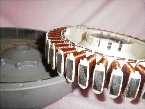
This shows poles twisted then high spots removed. Should have take you about 15mins..... Exactly what breed do you have 60, 80 or 100S, these represent the wire size 0.6mm, 0.8mm and 1.0mm diameter wire (roughly, dont get carried away with the digital vernier) If you have 100S (lucky you) then I would be surprised if you got much at all but if you have a 60S then be VERY careful spinning it to 600 rpm as the shock may be lethal. Try some rectifiers on all three phases so you have some better measurable voltage as the three (single) phase is very high frequency thus you meter might not give a good indication. Hence be careful! i'd be trying for 4x 50W 12V globes in series, this gives you 48V handling no probs and an 80S is the most commonom 48V for 48V systems we run them in 2X7C (split in half and paralleled) and we get cut in at 200 odd rpm -hence yours should be half that as all yours are in series hence twice the voltage. Luck favours the well prepared |
||||
| dvn8 Newbie Joined: 04/01/2010 Location: Posts: 10 |
Hi Karlj, You're probably wondering why it took me ages to de cog is that I had to make my own new tool to twist the poles 10 degrees angle - found a piece of steel in the shed. I don't have the proper tool to sand the high spots and I used an old filing, took me 2 hours to do all that. Not really in a hurry to complete the project. I have ordered the stator on ebay and got it configurated as 3 stars so I need to re-wire it into 7 phase. It is 80s series. I need to get the rectifiers and newer version of magnet hub. Where can I get the globes 50W 12 volts? I was wondering if there are ways to light up the light efficient globes as those are only powered by AC? |
||||
| KarlJ Guru Joined: 19/05/2008 Location: AustraliaPosts: 1178 |
No 7 phase for you. De-cogging is only done when you run normal 3 phase, 7 phase motors dont cogg anyway, due to the config of the magnets there are no longer any magnetic lumps to get over. For filing the stator I use an angle grinder with a flap wheel, normally I just knock off the high spots as shown in the pic or bolt the stator to the bearing block with the shaft, hang onto the shaft and use the angle grinder to true it up whilst spinning, doesnt take much and takes probably 20mins all up. COnfigured with 3 stars? mmmm show us a pic of the stator it has 42 poles thus normally would end up with, two or seven depending on the voltage you were looking for. If you have three star points now then, its probably already 7 phase hence no output with the magnet hub you have but you got 30V so I'm a little stumped. 50W 12 volt globes are easy, car headlight bulbs, 12V downlights etc. Buy some of these from Jaycar or equivalent Ebaybridge recs FOr 7 phase you will need 4 of them and for three phase you will need 2 of them, now that I have some experience under my belt I'd go for three phase and have each Phase on its own REC as shown on the otherpower forum F&P rectifier That massive heatsink is not required for F&P size mill but I would recommend bolting them to a piece of Aluminium angle 1"x 1" with an inch between each one at or some heatsinks extracted from a PC power supply (hard rubbish they are everywhere) Jaycar do have some that suit the square ones nicely but you'll spend almost as much on the heatsink as the recs. Something like this may be a cheaper option and work just fine for three phases 90A bridge rec 3 phase Personally unless your stator is already rewired for 7 phases and now that you have de-cogged it i would consider doing Gordons cap mod with your spare $$ rather than buying a later series magnet hub. My opinion here is simple, if after de-cogging a regular 3 phase F&P there is not enough wind to turn it, then there simply isnt enough wind! keep us posted Luck favours the well prepared |
||||
| GOFJ Newbie Joined: 22/12/2009 Location: AustraliaPosts: 27 |
Checked the voltage figures last night, unmodified 80 series at 400 RPM gave (open circuit) one phase 147VAC and one leg 86.5VAC Jack |
||||
| KarlJ Guru Joined: 19/05/2008 Location: AustraliaPosts: 1178 |
mmmmm LETHAL! Luck favours the well prepared |
||||
| dvn8 Newbie Joined: 04/01/2010 Location: Posts: 10 |
I have took some photos of the stator and I have no idea how to post them. 7 phase is used for the low rpm, is that correct as I am aiming for a low rpm and low cog. Also I have noticed that there are a bit of friction in the shaft and the bearing tube, I was thinking if I take off the bearing tube and put in 2 ball bearing and that will spin more freely? Does the newer magnet hub helps more to de cog? While I was cleaning up my workshop and the stator from all the dust and metal dust while filing the stator, I noticed there was a pole that has cut open the wiring cover, does that affect the stator's efficiency? |
||||
| KarlJ Guru Joined: 19/05/2008 Location: AustraliaPosts: 1178 |
post pic with the tree and arrow above the window you reply in easy keem em small. Luck favours the well prepared |
||||
| dvn8 Newbie Joined: 04/01/2010 Location: Posts: 10 |
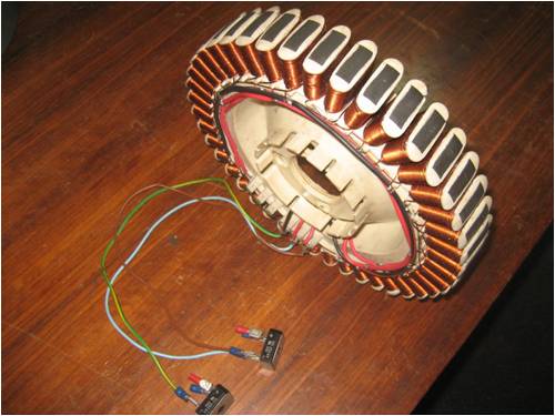
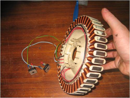
Here are the images of the stator. 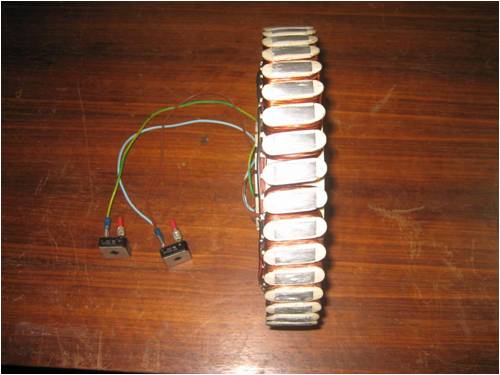
|
||||
Greenbelt Guru Joined: 11/01/2009 Location: United StatesPosts: 566 |
dvn8; I have never seen a modified F&P other than pictures, The one you have pictured here appears to be short on the number of output wires, I see what looks like 6 output terminals which I would expect but no wires coming off them to the diodes.The phases may be short circuit at the diode connection. this would surely make it difficult to spin. The 2 black wires circulating the stator is probably the pair of one phase The Red another phase, The third is not visible here, may be at the terminal strip solderded directly. I don't understand the bare wire connected to the diode, maybe some one can enlighten me on this. I'm waiting for the ozzie ax to fall!.. This is how I see it.if this be wrong? Let it fall. PS. You can learn about the back to back capacitors when you get some voltage showing. Hang in there you have a good start. EDIT; Re draw image to show terminal jumper wire on AC. Output X Y Z. 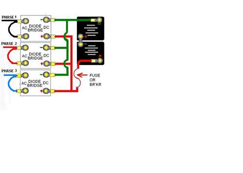
Time has proven that I am blind to the Obvious, some of the above may be True? |
||||
Downwind Guru Joined: 09/09/2009 Location: AustraliaPosts: 2333 |
What is the stator wired for star or delta?? What config of coils have you used. Pete. Sometimes it just works |
||||
| KarlJ Guru Joined: 19/05/2008 Location: AustraliaPosts: 1178 |
Looks like the stock rewire for 7x2C in Star to me Well Done! Chopped every six coils apart and wired accordingly. OK to share a rec across two phases. I trust you have bolted the magnet hub on the shaft and bearings and given her a spin now the rewire is done? If she still spins (generally you have got it right) Now that she's reconnected no more lethal voltages being generated, thats good to. re making the shaft run more freely in the hub. Knock out the bearings, using a small screwdriver, pick the seal out of ONE SIDE only. put one back in with a little loctite on the bearing in the bearing mount with the exposed side in the middle, put the spacer back in put the other bearing back in also with the missing seal on the inside (also loctite to housing), add a good squirt sewing machine oil / any oil, carefully re-insert the shaft and loctite it in there too. This should keep the oil in at least for a while and reduce seal drag by 50% Karl Luck favours the well prepared |
||||
| dvn8 Newbie Joined: 04/01/2010 Location: Posts: 10 |
I haven't had the time to really have a good look at the S & D lately as am pressed for free time lately. I will post some more photos later as I will re wire the stator to 7 phase and fix the bearing. So how do you remove the seal from the hub? thanks |
||||
| KarlJ Guru Joined: 19/05/2008 Location: AustraliaPosts: 1178 |
Carefully knock the bearings out of the hub, loose the water seal pry it out with a screwdriver. pick the seal out with a small screwdriver -easy as pie. I still dont think 7 phase is the go as you'll need the other 36pole magnet hub -I've never seen one and as new part they are $150+ bucks. The very latest 36Pole hub has 20% bigger magnets so if you can get this then go for it. big mag hub A seven phase conversion to an 80S with these should work well into 48V too, just the voltage doubler would stop me doing it as Gordon hasnt published anything for those and 7 phases is LOTS and LOTS of CAPS....like 28 to be precise. would need fistfulls of rectifiers too, thinking too complicated when 100% gain can be had Luck favours the well prepared |
||||
| Tinker Guru Joined: 07/11/2007 Location: AustraliaPosts: 1904 |
I doubt the 48V bit Karl. I do have my 80S converted to 7 phase with the new magnet hub which, BTW, was only about 1/2 the price you quoted. The coils are arranged in 2 parallel groups of 3 in series, star connected. I was hoping my Lenz2 would spin the thing fast enough to charge my 24V battery bank but that only happened briefly in a gale.... Perhaps for a really fast spinning HAWT it could work on 48V. 7 phase capacitor voltage doubling is only for those who do not have to *buy* the capacitors  in my humble opinion. in my humble opinion.
I am now tinkering with 3 phase and capacitor doubling, don't know yet what I'll do with the 7 phase F&P. Klaus |
||||
| GWatPE Senior Member Joined: 01/09/2006 Location: AustraliaPosts: 2127 |
I did buy one of these new magnet hubs "new" for $76. I gave it away, as I had finished my F&P testing. Gordon. become more energy aware |
||||
| KarlJ Guru Joined: 19/05/2008 Location: AustraliaPosts: 1178 |
Sorry, Sorry, I was quoting ecoinnovation's prices for the 20% stronger magnet hub. We do have a forum member Dave who runs 7 phase into 48V, max 600W with normal 36pole magnet hub. It is a HAWT with fairly small blades so i guess its HOOTING along! I assumed (wrongly of course) that the spare part would be similar price to ecoinnovation as some of their other parts are about right with new bits EG bearings. Luck favours the well prepared |
||||
| The Back Shed's forum code is written, and hosted, in Australia. | © JAQ Software 2026 |
