Notice. New forum software under development. It's going to miss a few functions and look a bit ugly for a while, but I'm working on it full time now as the old forum was too unstable. Couple days, all good. If you notice any issues, please contact me.
isaiah Guru Joined: 25/12/2009 Location: United StatesPosts: 303
Posted: 11:04pm 16 Feb 2010
Copy link to clipboard
Print this post
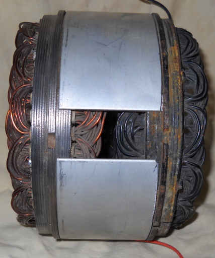
I am talking with some friends about stretching the case on a gm alternator(10 or12 si) to accept 2 stators. Is there any problem with how close to each other the stators are?
I was thinking 1/4 inch between them max?
This would make a system similar to The F & P doubles.
The stretched alternator should wind up around 2 inches longer than stock. There is one problem with the fit up but I think I can work it out.
We could use two permanent magnet rotors or make a new one long enough to serve both stators. Install magnets to suit.The GM Alternators are still readily available in the USA. I have a couple pictures on Bubs camera Ill try and get up in a day or so. This resizing the pic's is a pain.
CharlieURL=http://www.motherearthnews.com/Renewable-Energy/1973-11- 01/The-Plowboy-Interview.aspx>The Plowboy Interview[/URL>
MacGyver Guru Joined: 12/05/2009 Location: United StatesPosts: 1329
Posted: 02:45am 17 Feb 2010
Copy link to clipboard
Print this post
Isaiah
I see a problem, but it is in the basic premise. The GM alternator is really small in diameter compared to that of an F&P. I'm finding out building my own alternator from scratch that the larger the diameter, the slower it can turn and still produce usable electricity.
Being smallish, the GM alternator has to turn at 10,000 rpm (from memory) in a car before it starts producing juice. For this reason alone, my future builds will likely be larger in diameter.
. . . . . MacNothing difficult is ever easy!
Perhaps better stated in the words of Morgan Freeman,
"Where there is no struggle, there is no progress!"
Copeville, Texas
isaiah Guru Joined: 25/12/2009 Location: United StatesPosts: 303
Posted: 03:25am 17 Feb 2010
Copy link to clipboard
Print this post
This is a tentative Idea. URL=http://www.motherearthnews.com/Renewable-Energy/1973-11- 01/The-Plowboy-Interview.aspx>The Plowboy Interview[/URL>
isaiah Guru Joined: 25/12/2009 Location: United StatesPosts: 303
Posted: 03:33am 17 Feb 2010
Copy link to clipboard
Print this post
MacGyver
If you get a stator for 24 or 48 volts and a permanent magnet rotor it will cut in much lower
Bub has one with the 24 volt stator and one of those rotors off ebay
that puts out useful voltage at 200 rpm.
Thus the Idea for two stators one wound for low wind the other for average wind speed.
We figure on putting the rectifier and caps or what ever down at the combiner box.Edited by isaiah 2010-02-18URL=http://www.motherearthnews.com/Renewable-Energy/1973-11- 01/The-Plowboy-Interview.aspx>The Plowboy Interview[/URL>
oztules Guru Joined: 26/07/2007 Location: AustraliaPosts: 1686
Posted: 03:46am 17 Feb 2010
Copy link to clipboard
Print this post
[quote]Thus the Idea for two stators one wound for low wind the other for average wind speed[/quote]
Take care to bench test it in this configuration. The F@P does this quite well because of it's high armature reactance.
This means the low wind winding, "current limits" when the big wind turns up,(and protects it from burnout) and a different stronger stator could take the bulk of the remaining power (with much less turns and higher rpm).
In a car alt with strong neo's, it may not current limit before burn out of the low power coil, as reactance may not current limit it soon enough to keep it safe.
just a thought.
..........oztulesVillage idiot...or... just another hack out of his depth
Perry Senior Member Joined: 19/11/2009 Location: Posts: 190
Posted: 08:53am 17 Feb 2010
Copy link to clipboard
Print this post
I think you are really going through a lot of trouble to make a 300 watt generator. Just my perception. Traditionally converted car alt's have been pretty low performers.
Beyond that, you'll need to reinforce the bearings as they won't support that large of a rotor.
Perry
Downwind Guru Joined: 09/09/2009 Location: AustraliaPosts: 2333
Posted: 12:11pm 17 Feb 2010
Copy link to clipboard
Print this post
Bearings were my thought to.
Thats if these alts have bearings and not bushes.
I have seen some discussions that the bigger cased alts make a reasonable generator but the smaller car ones are p....poor as a alt.
Think there was some good discussions on fieldlines a while back that might be worth hunting down for a read before going to far with the build.
Pete.Sometimes it just works
isaiah Guru Joined: 25/12/2009 Location: United StatesPosts: 303
Posted: 03:06pm 17 Feb 2010
Copy link to clipboard
Print this post
Oztules
What is reactance ?
What is the 3 in hand of rewiring the coils on the stators?
How dose one ever keep track of all those turns and that you got them wound in the right direction?
The bearings should be no problem They are made in Hong Kong.
One of the motors I have up and running now uses 2 of the same bearings!the Delco uses and it weighs 22 lbs and the rotor in it quite heavy!
The delco uses a needle and roller bearing I was thinking of making the new shaft so I could use the roller bearings on both ends by using two front housings and I could put blades on both ends. URL=http://www.motherearthnews.com/Renewable-Energy/1973-11- 01/The-Plowboy-Interview.aspx>The Plowboy Interview[/URL>
Perry Senior Member Joined: 19/11/2009 Location: Posts: 190
Posted: 01:59am 18 Feb 2010
Copy link to clipboard
Print this post
hmmmmmm :)
oztules Guru Joined: 26/07/2007 Location: AustraliaPosts: 1686
Posted: 10:01am 18 Feb 2010
Copy link to clipboard
Print this post
[quote]Oztules
What is reactance ?
What is the 3 in hand of rewiring the coils on the stators?
How dose one ever keep track of all those turns and that you got them wound in the right direction?[/quote]
1. Armature reactance for these purposes works like this.
You have your neo magnets in the rotor that put out X lines of force that act on your coils. Open circuit voltage may be say 12vac @ 200 rpm. It is because of those lines cutting the copper turns of T turns, that we get a certain EMF generated in those coils.... this gives you your rpm/volt.
Now we put it under load. Not just volts (EMF) are in the copper now, but current is flowing as well. Flowing current generates a magnetic field around itself. It will work in opposition to the magnetising force (the neo's). This degrades the value of the X flux lines, as now we have X-(whatever the stator is now opposing it with.)
The nett result is that we have less lines of force to actually cut the copper now, as some of them have been repelled... so we now get less voltage (EMF) generated in the wire, and the terminal voltage will be the generated EMF-volts lost in the stator via current X resistance.
You can see where this is going now, the more we draw current out of the stator, the more magnetic flux lines get deviated away from the stator, and more insult to injury is the volts lost in the coils goes up as well... we lose everywhere.
Now this "reverse" magnetic field the stator is making in opposition to the Neo magnetic field is called back MMF (magneto motive force). It's value is proportional to the Ampere Turns. So the back MMF goes up if the amps increase or the number of turns increase. We can't change the turns on the run, but we can certainly increase the amperage by increasing the rpm.
It will get to a point where as we get the rpm's up high enough, that our back MMF will oppose the neo field so much, that no matter how much faster we spin it, no more power is forthcoming.... we are now current limited. The amp turns are now such that we can get no more EMF into the coils because we are repelling enough flux to achieve an equilibrium....
Now if we have the turns and wire size and sufficient heat sinking from the stator iron (F@P) right, we can do this indefinitely, and not burn out the stator from the I^2 R losses in it... If our neo's are strong enough, and our turns low enough (amp turns remember), we may not get to current limiting before our low efficiency stator cooks.
An F@P has feeble magnets and good cooling and high turns count.... it will probably current limit before burning out. A car alt will have much less turns, and big neo's. Much harder to deflect the field away from the stator.
So if you wind a low wind speed stator, it will have lots of turns of thin wire, and become subject to much greater I^2 R losses..... heat.... poof....
So long story short:
If you design it so that your flimsy low wind winding will current limit at say 5A, and no matter how much faster it spins, it will always be 5A, then it can't burn, and the big wind winding takes over. The little one will continue to contribute the 5A as well... win win..... otherwise as rpm increases, the little one will eventually cook unless this happens.
2. 3 in hand means using three spools of wire and winding them onto the coil former as if they were one... ie. 3 at a time.
3. You keep track of them because the three wires are treated as one.... 3 at once as if they were one only.
......oztulesVillage idiot...or... just another hack out of his depth
isaiah Guru Joined: 25/12/2009 Location: United StatesPosts: 303
Posted: 02:40am 19 Feb 2010
Copy link to clipboard
Print this post
So if I were to put both stators the same and both rotors the same it should work without too many problem?
We dont throw anything away so maybe Ill look up some of the old stock stators as the different amp alts use different size wire so I might try it before I spend any money on boughten or rewound ones.
I have a old truck alternator that the rotor and stator are the same dimensions as the 10 & 12 si but it has a heaver finned case and heavier bearings I think Ill use for this project.
Dose any one have any input on the gm alternators were called permanent magnet that were used on the older semi trucks. these were not a true pm but has some sort of pm to excite the stator. I have one but haven't torn it apart it also is 35 lbs.
Thank You for the reply.URL=http://www.motherearthnews.com/Renewable-Energy/1973-11- 01/The-Plowboy-Interview.aspx>The Plowboy Interview[/URL>
Bub73 Senior Member Joined: 10/12/2009 Location: United StatesPosts: 116
Posted: 10:34pm 20 Feb 2010
Copy link to clipboard
Print this post
@ oztules;
Thanks for the detailed explanation, it helps me understand whats going on in there.