Notice. New forum software under development. It's going to miss a few functions and look a bit ugly for a while, but I'm working on it full time now as the old forum was too unstable. Couple days, all good. If you notice any issues, please contact me.
MacGyver Guru Joined: 12/05/2009 Location: United StatesPosts: 1329
Posted: 07:14am 26 May 2010
Copy link to clipboard
Print this post
Crew
For a while now, I've been tempted to build some larger iron-cored windmill generators. The biggest problem with this approach is the windmill needs maximum starting torque to release the magnets' grip on the iron when the wind slows or stops. Centripital clutches, like the ones on mini-bikes work, but when they grab on, it puts a horrible strain on the blade attachment and sooner or later all the stop-and-go bumping takes its toll in the form of a cracked-off blade and almost immediate destruction of things when a blade flies off at speed.
As a way around this, I have designed (but not built yet) a mechanical system that uses springs and flyweights to adjust the pitch from a default setting of 45 degrees to a maximum (actually minimum) pitch of 10 degrees. The default pitch will yield the most starting torque, while the other end of the spectrum will yield the greatest shaft speed. Together the pitches will carry the windmill through fast and slow wind.
One problem that this design has is each blade must work at exactly the same pitch and all the blades' pitches must change at the same time. If the blades don't adjust in unison, an unbalance occurs and the thing shakes itself apart. Movement of the individual blades must be both sure and in equal proportion to the rest of the blades.
Study the following two diagrams I've drafted. I'll leave this here until I have the time to machine the thing. Right now, I'm waiting for materials to finish my axial-flux toy windmill as well as one that is iron-cored (and will likely cog like there's no tomorrow!). In the meantime, if anybody has any thoughts, post them here and together we'll iron out the details so when it's time for the build, the final product should work. At least, that's the plan.
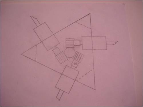
This is the hub end. The large triangle is made of welded aluminum. The blades pass through a bushing, which is pressed into an aluminum tube welded to the aluminum triangle hub frame. A stop at both the inboard and outboard side of the bushing shaft keeps it in the proper position. There is a spur gear fastened to the end of each blade shaft using a set screw. I see now I forgot to draw two of the set screws in, oops! The spur gears are locked into a rack gear (like rack and pinion steering) which "floats" freely on the end of the windmill's shaft, positioned by a spring trapped between the outboard side of the hub and an inner, moveable hub wall that is controlled by flyweights (see second picture). The little dotted lines in the corners of the triangle are gusset welds inside the hub. These hold things true under stress.
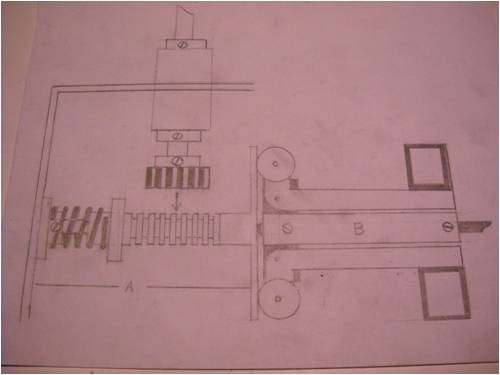
From left-to-right we see the "A" portion, which floats freely on the windmill's shaft. The spring tries to force the rack into the "default" blade position (45 degrees to the wind direction). The "B" portion is locked onto the spinning windmill shaft. The two round things are little wheels, which ride on the "floating" hub wall of the piece carrying the rack gear -- the "A" part -- which pushes tension aft via the spring. The two dark square boxes on the "B" side are flyweights. The "B" part, being locked to the spinning shaft, twirls as the blades provide the motive force. As the weights spin, centripital force throws them outward and as this happens, the action moves the bell crank (lever) and the little wheels work in unison pushing the moveable rack hub plate and change the position of the rack, which in turn rotates each of the blade shafts in unison (or so the plan goes!). The picture shows two flyweight setups, but in reality, there will be three, each set 120 degrees from the other two.
Well, that's it. Now it's everyone else's turn to shoot at it and maybe we can come up with a better mousetrap, who knows?
. . . . . Mac
Nothing difficult is ever easy!
Perhaps better stated in the words of Morgan Freeman,
"Where there is no struggle, there is no progress!"
Copeville, Texas
Hey Mac, sounds like a runner. I'm wondering about over-speed protection though. Traditional furling? I don't know how having a system that promotes an ever-decreasing angle of attack as wind speed ramps up will survive long term, from what I've read (and understood).
Don't self feathering hubs start at slight attack angles and rotate away from the wind (towards larger attack angles) to decrease their efficiency? I know that a higher attack angle improves yielded torque (great for start-up) but at speed it is countered by the dramatic aero inefficiencies as air flows badly over the blade. I'd welcome correction on my understanding if I'm way off here.
I understand where you're coming from with the "start large (angle of attack) and progress to efficient" but I suspect you might need to limit the attack angle you end up at if you live in a windy region. Indeed, if I'm actually on the right path, the windier the set-up, the larger the final attack angle will need to be for longevity.
LukeEdited by montyLalor 2010-05-27"So are you doin' this project to make us money or cost us money?" she asks again...
wind-pirate Senior Member Joined: 01/02/2007 Location: CanadaPosts: 101
Posted: 03:03pm 26 May 2010
Copy link to clipboard
Print this post
Hi Mac
The Idea of a regulating hub has been around for some timr now.
What is the best idea?
I liked your earlier idea "The Drill bit thing"
Teamed to:
(One) rotating plate. Keeping all 3 blades the same...
(One) Spring. Adjustable maybe.....
Starting out at (ABOUT) 45 deg. and droping off to Zero "or maybe even Negative" to slow it down. a person would have to do some expermenting, Speed regulation / noise.
Just a thought >>>>....
Ron THE Pirate.
stealing wind & solar energy is fun
MacGyver Guru Joined: 12/05/2009 Location: United StatesPosts: 1329
Posted: 04:51pm 26 May 2010
Copy link to clipboard
Print this post
montyLalor & wind-pirate
Both good posts; thanks each. Yes, there's more to this than I've posted, but I didn't want to belabor the initial post with too much rhetoric. I wanted the crew's input instead.
First off, I had thought about the over-speeding and decided I might be able to allow the travel on the rack to go to such a point that the blades went flat against the wind or even reversed pitch a bit. Flat, spinning blades present quite a large wind "footprint" in the wind, sort of like holding a piece of plywood at arm's length flat against a wind -- lots of tower stress -- but that's likely the case. I don't see any way around that one, except to limit the length of the blades.
The drill-bit thing I posted a while back in the days when Dinges was a regular visitor also passed through my mind, but that one is better suited for a single blade application. I've built single-blade windmills before using a counter weight to offset the blade and maintain balance, but these things scream and their speed is very hard to control. They basically have two speeds, stop and full-on maximum. Using the hollow blade-mount tube sliding down a drill-bit flute and twisting with longitudinal movement is a tricky thing to do to get all three blades at the same pitch at the same time. The machining has to be spot on and I don't know how wear might figure in, so that's one I'm leaving on the drawing board for a while.
Now that I think about it, the single-blade machine is somewhat of a constant intrigue. It has two really big problems or I'd build them all the time. The build is super simple, but they have a hard time turning (furl / yaw) and as the single blade passes the tower, the "wind shadow" of the mast, it causes the whole thing to bump. Kinda like "coggging" using magnets and iron cores does, this thing just "beats" almost sub-audibly, but enough to drive you nuts.
What doesn't show in my original posting is the tail. I also design and build sail planes (R/C) and have a lot of experience with "controlling surfaces" translating small movements into large motions. The tail on this windmill will have a rudder.
On one side of the rudder will be a "bell crank". That's a lever shaped like the letter "L" with its pivot point at or near the bend. This lets you pull one end in one direction and create movement on the surface at the other end at 90-degrees from the initial position.
In this case, I'd install a spring-loaded bell crank on the rudder. The spring would keep tension on the rudder, but it would be "pinned" in position by a little piece of round metal (a pin!). In the case of over speeding, the pin could be yanked out either by someone on the ground pulling the little string that dangles under the rig or by servo-mechanical means built into the fly-weight system. When the pin comes out of its land, the rudder slams to one side, turning the entire windmill out of the wind.
Unfortunately for this system, if activated, the mill would have to be reset manually, meaning either climbing the mast or lowering the windmill. Better than destroying everything, but a pain in the drain as well.
Something to remember here: Everything I build is really little! I like building little stuff, so increasing all the sizes to make this practical for someone desiring to generate "house current" on the order of being able to grid tie, would mean some serious re-engineering. It's one thing having 30-inch blades whirring around, but 10-foot blades are another realm altogether!
I suppose I could don the thinking cap and come up with a way to incorporate extreme movement of the fly weights acting on a cam or something that would gradually adjust the rudder to pull the thing 'gently' out of the wind's path preventing overspeeding, but like I said before; drawing-table stuff!
Of course, the basic idea presented here could be built into a design that doesn't require the reverse of normal, meaning it could be used to pitch the blades steeper as the speed increased, thus making it a true over-speed protection application. I just attacked it from the other side of the coin to meet my 'particular' need. Once we've hashed over al the "bugs", feel free to build and use the design however it fits your situation.
. . . . . Mac
Edited by MacGyver 2010-05-28Nothing difficult is ever easy!
Perhaps better stated in the words of Morgan Freeman,
"Where there is no struggle, there is no progress!"
Copeville, Texas
readyakira Senior Member Joined: 17/07/2008 Location: United StatesPosts: 114
Posted: 06:34pm 26 May 2010
Copy link to clipboard
Print this post
dont cars do this in opposite mode with flex fans? in a car the force straightens the fins, in a windmill the flex part of the blades would just need a diff wider range of pitch?Don't you think Free/Renewable energy should be mandatory in new buildings?
MacGyver Guru Joined: 12/05/2009 Location: United StatesPosts: 1329
Posted: 07:30pm 26 May 2010
Copy link to clipboard
Print this post
readyakira
You are partially correct. I tried this once back in the day, but found the tensile strength of the fans was such that at extremely-high rpm, they unfold a bit. I tried it with a windmill blade, but it was not controllable. I even thought of (but never tried) building a controlling surface like an aileron on the trailing edge of the blade activated by a fly-weight somehow.
If it could be made to work with larger, slower-moving blades, it would be the bees' knees! Maybe you could goof around with it and find a way, ya think?
. . . . . MacNothing difficult is ever easy!
Perhaps better stated in the words of Morgan Freeman,
"Where there is no struggle, there is no progress!"
Copeville, Texas
MacGyver Guru Joined: 12/05/2009 Location: United StatesPosts: 1329
Posted: 07:39pm 26 May 2010
Copy link to clipboard
Print this post
Woah!
I just came up with a way-easier way to do this whole thing. I'll draw it up and post it here later today or tomorrow.
This is the benefit of "brain-storming". It dips into everyone's creativity bucket and who knows what might get dragged out?
Stay tuned.
. . . . . MacNothing difficult is ever easy!
Perhaps better stated in the words of Morgan Freeman,
"Where there is no struggle, there is no progress!"
Copeville, Texas
neil0mac Senior Member Joined: 26/12/2009 Location: AustraliaPosts: 210
Posted: 10:19pm 26 May 2010
Copy link to clipboard
Print this post
Use a spring loaded solenoid operated "pin" so that it could re-engage when the need to release the "pin" was removed?
MacGyver Guru Joined: 12/05/2009 Location: United StatesPosts: 1329
Posted: 06:27am 27 May 2010
Copy link to clipboard
Print this post
[Quote=nenil0mac]Use a spring loaded solenoid operated "pin" so that it could re-engage when the need to release the "pin" was removed?
That's great, but it doesn't solve the problem of moving the spring-loaded rudder back into a "trim" position. Either you climb up the tower or bring the rig down, cause someone's gotta re-cock that rudder!
. . . . . Mac
Nothing difficult is ever easy!
Perhaps better stated in the words of Morgan Freeman,
"Where there is no struggle, there is no progress!"
Copeville, Texas
grub Senior Member Joined: 27/11/2007 Location: AustraliaPosts: 169
Posted: 09:50pm 27 May 2010
Copy link to clipboard
Print this post
How about a tail vane that lifts as the wind speed increases. This in turn either pushes or pulls the shaft and thus changing blade pitch. As the wind drops, so does the tail vane. This then allows the shaft to move back to its orginal position. There would even be no need for the return spring.
MacGyver Guru Joined: 12/05/2009 Location: United StatesPosts: 1329
Posted: 12:07am 28 May 2010
Copy link to clipboard
Print this post
grub
Not sure there would be enough power to actually change anything. Build it and we'll all take a look at it. At present, I already have too many plates in the air to add any more.
On top of that, my MacBook's screen backlight took a dive. I'm on one of my other Macs for the time being until either my laptop gets repaired or I fork out the green for a new one ($1K)!
. . . . . Mac Nothing difficult is ever easy!
Perhaps better stated in the words of Morgan Freeman,
"Where there is no struggle, there is no progress!"
Copeville, Texas
MacGyver Guru Joined: 12/05/2009 Location: United StatesPosts: 1329
Posted: 03:36pm 28 May 2010
Copy link to clipboard
Print this post
Crew
Thank you, crew member "vasi" who instructed me on how to fix my computer! It works again.
I think I may have nearly worn out the thinking cap, but I've come up with a way to do the variable-pitch thing as well as another similar system on the same windmill, which will proportionately "furl" the rig using a controlled rudder on the vertical stabilizer (tail) should the blades overspeed.
If you like machining lots of small parts, you'll LOVE this project. Rather than belabor the board here, I'll build it and throw the details up after it's flying.
I'm somewhat of a techno-dummy when it comes to stuff like making movies and posting to You Tube and all, but I have kids that popped out of the womb with computer knowledge, so I'll hopefully have some flicks to share sooner or later for all this.
Until then,
. . . . . MacEdited by MacGyver 2010-05-30Nothing difficult is ever easy!
Perhaps better stated in the words of Morgan Freeman,
"Where there is no struggle, there is no progress!"
Copeville, Texas
MacGyver Guru Joined: 12/05/2009 Location: United StatesPosts: 1329
Posted: 05:03am 02 Jun 2010
Copy link to clipboard
Print this post
Simpler Design
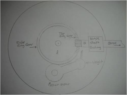
Okay; I'm back with a much simpler design. The only really hard part is either finding and adapting the gears or making them from scratch. Broaching a top ring gear with a spur ring gear on the side of the same piece would be quite a "weekend project" but if anyone is up to it, be my guest. Here's a barely-visible sketch of what I'm up to:
The way this works follows:
First off, what is shown here is only one blade-pitching mechanism. In the final build, there would need to be three such items, each placed at 120 degrees from the other two, pitching each of three blades simultaneously.
As the whole shebang turns in the wind, the flyweight (labeled "weight") would be thrown out against the little spring, which tries to hold it inboard near the central hub. When it begins sailing outbound, being attached to a spur gear, which is meshed to the side ring gear of the main hub, it rotates the spur gear, which in turn rotates the central hub. The central hub sits on a ball bearing at its center and everything is mounted on a plate which also supports the blade shaft bushings.
On top of the central hub (A) is another ring gear cut into it's top face along its circumference.
At "B" there is a spur gear attached to the blade shaft. That spur gear is meshed to the top ring gear of the main hub and as the hub rotates, due to the action of the flyweight rotating the spur gear(s), it in turn rotates the blade shaft, changing its angle of attack to the wind.
That's about it; easy huh?
Like I said, the only "real" problem is broaching that central hub so it has a ring gear both on its side and on its top circumference. Because of this fact and that I already have way too many plates in the air, I'll likely use levers acting on pins for my first build of this sucker.
Stay tuned and as I find the time, I'll try to fit together something that works and I'll post it here. I'll likely just post the finished project and not a blow-by-blow build simply because the design will likely change by the time it's a done deal.
. . . . . Mac
Edited by MacGyver 2010-06-03Nothing difficult is ever easy!
Perhaps better stated in the words of Morgan Freeman,
"Where there is no struggle, there is no progress!"
Copeville, Texas
wind-pirate Senior Member Joined: 01/02/2007 Location: CanadaPosts: 101
Posted: 04:10pm 02 Jun 2010
Copy link to clipboard
Print this post
Hi mac
Will that be able to control all three blades at the same time?
or will it be 3 seperate controls...
RonTHE Pirate.
stealing wind & solar energy is fun
MacGyver Guru Joined: 12/05/2009 Location: United StatesPosts: 1329
Posted: 04:19pm 02 Jun 2010
Copy link to clipboard
Print this post
[Quote=wind-pirate]Will that be able to control all three blades at the same time?
or will it be 3 seperate controls...
Yup! It'll do all three at once and as a matter of fact, that's the ONLY way this will work. All three blades have to trim at the same time and the same amount or it throws the mill out of balance and it'll thrash itself to pieces sooner if not later.
I only drew in one section, cause I'm a bit lazy is all. Imagine, if you will, two more flyweights and two more blades attached 120 degrees apart on that same hub and you'll have it.
. . . . . MacNothing difficult is ever easy!
Perhaps better stated in the words of Morgan Freeman,
"Where there is no struggle, there is no progress!"
Copeville, Texas
wind-pirate Senior Member Joined: 01/02/2007 Location: CanadaPosts: 101
Posted: 04:31pm 02 Jun 2010
Copy link to clipboard
Print this post
Hi Mac
I was sure you would do it right.
That should work. It worked on the old steam tractors.
Image If you will. "THE MacGYVER HUB" regulating the wind..
Simple is always best, but I think it is too easy to confuse mechanical with simplicity and reliability... and electronic with complexity. It can go either way and springs, weights and gears is not the way I'd go for a mill.
Have a look at the Ivoprop electrically adjusted prop.
http://www.ivoprop.com/inflightultralightmodel.htm
Picture on linked page doesn't show (have a look around for better) that it uses simple crank on blade ends in a slotted disk which (I believe) rotates with the shaft to twist the blades. Ignore the fact that Ivoprop twists the blade instead of turning it. The same principle works either way. Slotted disk is driven backwards and forwards by a screw. Stepper motor could probably be driven easy enough by a pic controller with inputs from airspeed, rpm and blade or motor position... or even a simple aoa sensor at a blade tip combined with rpm. This way you can always fly the blade at its optimum.
Projects like this are fun, but my opinion is that it is simply not worth it on small mills. For all of the time messing around to eek out a few more watts I'd sooner just build another or larger mill with fixed blades. Can't beat the KISS principle.
Cheers
Perry Senior Member Joined: 19/11/2009 Location: Posts: 190
Posted: 06:17am 09 Jun 2010
Copy link to clipboard
Print this post
Hey Mac,
I'd go with using a bell crank setup vs the ring gear. The ring gear looks good on paper but finding the gears you need is difficult. At least I came to that conclusion when I had the same idea. A cam type system could work as well.
Couple extra thoughts....no charge.
1. I think the variable pitch system is the most often started and least completed project posted on most boards. Myself included.
2. There really is no need whatsoever for pitch control on turbines these sizes. I wouldn't recommend one on anything under 100 kW personally.
Still, it's a lot of fun to think up these schemes.
Perry
Downwind Guru Joined: 09/09/2009 Location: AustraliaPosts: 2333
Posted: 10:55am 09 Jun 2010
Copy link to clipboard
Print this post
The single blade mill like you posted that NASA has would be a good system to play with variable pitch, as its only one blade and no balance problems of getting all blades to act together.
A simple spring or fly weight would be good enough for a single blade system,
It just looks goofy.
Pete.Sometimes it just works
Jarbar Senior Member Joined: 03/02/2008 Location: AustraliaPosts: 225
Posted: 11:22am 09 Jun 2010
Copy link to clipboard
Print this post
Or have a look at this one.
http://www.youtube.com/watch?v=XZE8jGHxnr4
Anthony.Edited by Jarbar 2010-06-10"Creativity is detirmined by the way you hold your tounge".My Father
"Your generation will have to correct the problems made by mine".My Grandfather.
Page 1 of 2
Print this page
The Back Shed's forum code is written, and hosted, in Australia.