
|
|
Forum Index : Windmills : COFAZING AC AT MAST
| Page 1 of 2 |
|||||
| Author | Message | ||||
| GADGETS Newbie Joined: 10/03/2010 Location: AustraliaPosts: 8 |
 I HAVS BEEN GOING THROUGH THIS WEB SIGHT FOR 2/3 YEARS ANLY RECENTLY BECAME A MEMBER. I AM ABOUT TO FINISH BUILDING MY FIRST DUAL F&P WINDGEN. I HAVE THOUGHT OF COFAZING THE AC AT THE TOP, THUS SAVING RUNNING SO MANY WIRES DOWN THE MAST. I'VE THOUGHT OF USING DIODS IN BETWEEN TO STOP VOLTAGES FROM FAZE TO THE OTHER. ANYONE HAS ANY IDEAS ABOUT THIS? I HAVS BEEN GOING THROUGH THIS WEB SIGHT FOR 2/3 YEARS ANLY RECENTLY BECAME A MEMBER. I AM ABOUT TO FINISH BUILDING MY FIRST DUAL F&P WINDGEN. I HAVE THOUGHT OF COFAZING THE AC AT THE TOP, THUS SAVING RUNNING SO MANY WIRES DOWN THE MAST. I'VE THOUGHT OF USING DIODS IN BETWEEN TO STOP VOLTAGES FROM FAZE TO THE OTHER. ANYONE HAS ANY IDEAS ABOUT THIS?
CHARLIE |
||||
| dwyer Guru Joined: 19/09/2005 Location: AustraliaPosts: 575 |
Hi Charlie WhaT is COFAZING mean ? and good luck with your first dual F&P windgen and what about the blades? so can you able post some photo as everyone love to see your work of art. Good on ya 
Dwyer |
||||
| Gizmo Admin Group Joined: 05/06/2004 Location: AustraliaPosts: 5187 |
Hi Charlie, welcome to the site. I dont things its possible to cofaze, but you can rectify 
A 3 phase rectifier will combine the 3 AC feeds into a single DC feed, so you will only need two wires instead of 3. Is that what you meant? Glenn The best time to plant a tree was twenty years ago, the second best time is right now. JAQ |
||||
| GADGETS Newbie Joined: 10/03/2010 Location: AustraliaPosts: 8 |
Hi gizmo & Dwyer What I meant is to join output wires from one stator to the other ( from each faze) thus having only four wires (3 active one neutral) coming down the mast. I would prefer AC to the shed rather than then DC (less losses) |
||||
| GWatPE Senior Member Joined: 01/09/2006 Location: AustraliaPosts: 2127 |
Can you substantiate this. Real world measurements do not support this. Our colleageues accross the Tasman confirmed the opposite result you are claiming on a windmill.. Gordon. become more energy aware |
||||
| VK4AYQ Guru Joined: 02/12/2009 Location: AustraliaPosts: 2539 |
Hi Gordon How much lossier is the high frequency AC than the DC from the rectifier? All the best Bob Foolin Around |
||||
| Chipboy Newbie Joined: 13/12/2006 Location: AustraliaPosts: 16 |
If I understand you correctly, joining the different phases together will only do one thing, it will go bang. They are out of phase and consequently at different voltages referenced to each other. It should not / cannot be done. Pursue at your own peril. Matt PS, Please don't use CAPS, at its phase not faze, that is something you go through which may well happen if you do what your talking about Wind wannabe |
||||
| VK4AYQ Guru Joined: 02/12/2009 Location: AustraliaPosts: 2539 |
Hi Gadgets I understand what you are trying to achieve, and while it is possible to run two alternators together, in a coupled two rotor F&P it wouldn't be practical because even if you could synchronize the phases of both units any small differences in the stators would cause eddy currents to flow between the two stators, and cause power losses that would be translated into heating of the stators, while if synchronized accurately it would only be small loss any losses when you only have a small amount of power it is significant. To synchronize two alternators you need a coupling that is designed to allow small amounts of Phase angle to be accommodated. One alternator would become the master and the other the slave alternator. Good thought but not practical at this level of power. All the best Bob Foolin Around |
||||
| Gizmo Admin Group Joined: 05/06/2004 Location: AustraliaPosts: 5187 |
Ah, the penny just dropped for me, now I understand what Gadgets is up to. Yeah Bob is right, its going to be difficult to get both smartdrives lined up in phase with eachother. You need to either rectify the AC at the top and run DC down the tower, or run several wires down the tower. Normally we dont worry about the neutral(star) connection, but if you did want to run that down the tower, I think you could connect both neutrals together without any negative effects, so you would need 7 wires running down the tower. Trailer wire is 7 wire, I've used it before. Glenn The best time to plant a tree was twenty years ago, the second best time is right now. JAQ |
||||
| GADGETS Newbie Joined: 10/03/2010 Location: AustraliaPosts: 8 |
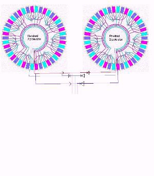
Hope the image comes throu as this is my first time. If it does would it work with the diods Charlie |
||||
| GWatPE Senior Member Joined: 01/09/2006 Location: AustraliaPosts: 2127 |
Pic is not real informative, but looks like you have a series diode, in each phase lead from each of the stators. Not sure what you are trying to achieve with this? I presume that you are hoping to use the star point as a centre tapping point for a 3 phase rectifier, on each stator. This is like a 2 diode arrangement for a centre tapped Xformer with full rectification, but for 3phase. You may be able to clarrify. Gordon. become more energy aware |
||||
Downwind Guru Joined: 09/09/2009 Location: AustraliaPosts: 2333 |
Basically you are trying to reinvent the wheel....Why???? Just use 2 x 3phase rectifiers, 1 for each stator. Then join the 2 DC positives together and the same for the negatives. Dont worry about the star point (or neutral as you called it) there is almost no point in using it with 3 phase. If your method was worth doing than many here would have done it years ago and it would be widely posted to the forum. Pete. Sometimes it just works |
||||
| KiwiJohn Guru Joined: 01/12/2005 Location: New ZealandPosts: 691 |
If the intention is to run two alternators and avoid the problems that Bob mentioned how about running the phases of one stator in series with those of the other stator? Higher voltages may or may not be what you need! |
||||
| VK4AYQ Guru Joined: 02/12/2009 Location: AustraliaPosts: 2539 |
Hi John Good point, as then two 12v configurations series-ed in phase for a 24 volt unit, however the accuracy of phase angle of the two still exists as there would be a lead lag effect on the waveform of AC and eddy currents again, I think it would negate the concept of a simple little system that could be got going for peanuts. To go to to that amount of trouble to get a bit extra power as compared to running a single stator with neo magnet rotor, I think a neo rotor would win hands down. It would be an interesting project to do the twin but not practical for a unit to do a job with minimum hair loss.
My twin that I am building isn't even rewired its just two stators reconfigured to delta coming down the mast to twin 3 phase rectifiers with a down converter from 110 volts to 30 volts when I get it finished I will post the project. All the best Bob Foolin Around |
||||
KarlJ Guru Joined: 19/05/2008 Location: AustraliaPosts: 1178 |
Ah but Bob, you're using my 100S stators right? most people are using an 80S which will need a rewire. My tip, drop the 6 wires down the pole using 2 15m 15A caravan extension cords, they are cheaper than buying the wire on its own. Use Gordons cap voltage doubler and let the harvesting begin. Of Interest my dual set a new record in the awful weather in Melbourne (Bairnsdale to be precise) it made 14.7KW for the day which for the first time since commissioning beat the 4.3KW solar array which due to the cloud cover etc only made 12KW for the day...  . .
Still averaging about 1.2KW/day since commissioning but with windy season upon us, i'm hoping the average will come up to 2KW/day. Not bad for a couple of old washing machine motors! Regards Karl Luck favours the well prepared |
||||
| GADGETS Newbie Joined: 10/03/2010 Location: AustraliaPosts: 8 |
Hi to everybody who has been kind enough to respond. WOW! I sure wasn't expecting such a response. I'm very grateful to you all. I'm not new to electronics;, but I am new to RE and that's why I put it on here. I know what electricity can do to the unwary. Maybe I am beeing a bit too cautious but it's better to be too cautious than dead. So it looks like I will rectify at the mast. I just don't like the idea of the rectifiers beeing out in the weather, but they will be in aluminium boxes which should also act as heatsinks. Hey Karl you're in bairnsdale not far from me I'm in Hollands Landing. Would like to meet you some day. if you like fishing & you fish here just ask at the shop where Charlie lives. There is one thing i forgot. I dont know if any body else has thought of this. While i was trying to decog a stator (Pretty crappy) I hit the coil with the file. OOPS! to solve this problem I bent a thin piece of aluminium in a u shape & leavingnthe open end slighly wider than the coil I slipped in over the coil.No more stuffing coils |
||||
| Downwind Guru Joined: 09/09/2009 Location: AustraliaPosts: 2333 |
Karl lives in Perth now, so its a long way to cast a hook. Or is that what the call "long line" fishing. 
You could bring the 2x3 phases down the tower with 7 core trailer cable like Gizmo surgested and place the rectifers at ground level. Im not a great fan of having electrics up the tower, as its a right pain if something goes wrong, and you need to lower the tower for a simple fix. Lets say in time you choose to add a capacitor doubler circuit to the mill and you will need access to the 3 phase to do this. There is many advantages to having the AC to ground level. Pete. Sometimes it just works |
||||
| GADGETS Newbie Joined: 10/03/2010 Location: AustraliaPosts: 8 |
Not much trouble to bring my mast down. I built it for ease of handling one man operation. I use an electric winch. Ineed something like that cause I got a bad back, so i got to watch not to put too much strain it. |
||||
| VK4AYQ Guru Joined: 02/12/2009 Location: AustraliaPosts: 2539 |
Hi Gadgets I go with Pete on the rectifiers out of the weather, between mud wasps and murphy it's a good idea to have them inside, and you can play with the volt meter on them as well, with due care and attention of course. I am using two leads 25 meters from bunnings at $16 each, I cut them in half and run double so its good for 20 amps a phase so as I am looking at a maximum of 6 amps shouldn't be a loss problem. As Im running 110 volts plus down the wire its not a lot of amps for 900 watts. Im using the original bearing assembly and have installed a extra bearing on the prop end to provide a bit extra support. The prop mounts on a split collet on the shaft to keep it as close to the bearings as possible. Two 3 phase rectifiers and four smaller bridge rectifiers for the doubler caps. At the moment I am waiting on a set of Neo magnets for both rotors so that will be an adventure fitting the magnets, by all reports of others that have done it they say from 50% to 100 % increase in output, so hears hoping. the neo magnets are so much stronger than the originals its unbelievable. Each little magnet pulls 3.5 Klg with two magnets per coil. My target is 1800 watts so hears hoping that works, I did get 900 watts per unit testing in the lathe at 650 rpm with the original magnets, out in the wind, well we will see. Im not to sure about your coil fix with a bit of alum did you cut the wire or just graze it? All the best Bob Foolin Around |
||||
| VK4AYQ Guru Joined: 02/12/2009 Location: AustraliaPosts: 2539 |
Hi Karl Good to hear that you got good figures now it makes the whole exercise worthwhile, That's a good setup and now you need to do it again in sandgropersville, I have been following your adventures, so keep up the good work. All the best Bob Foolin Around |
||||
| Page 1 of 2 |
|||||
| The Back Shed's forum code is written, and hosted, in Australia. | © JAQ Software 2026 |
