Notice. New forum software under development. It's going to miss a few functions and look a bit ugly for a while, but I'm working on it full time now as the old forum was too unstable. Couple days, all good. If you notice any issues, please contact me.
Hi all,
i have built 3 F & P mills and have one on a test stand & the other two in the waiting till i get everything right, i'm new to diy wind power and was wondering if there is any difference in performance when you run DC from the generator to storage (rectify at top of post) or run the 3 AC phases to just before storage (rectify immediately before charge controller and storage)
thanks glenn
KarlJ Guru Joined: 19/05/2008 Location: AustraliaPosts: 1178
Posted: 10:53am 23 Jun 2010
Copy link to clipboard
Print this post
Rectify at the pole on the ground.
there are heaps of posts on this topic but trust me, rectify at the pole.
KarlLuck favours the well prepared
Downwind Guru Joined: 09/09/2009 Location: AustraliaPosts: 2333
Posted: 12:20pm 23 Jun 2010
Copy link to clipboard
Print this post
Hi Bigdog,
It is really a matter of how long of a run you need to do from windmill to battery.
Karl is correct but there is advantages in running the AC to the batteries if the distance is not too far.
If practical i for one would much rather have 3 phase to batteries and all my control gear together in a shed.
This also allows greater flexability.
For long cable runs this is not practical as the cable loss is higher with "Wild AC"
I would not have the rectifier up the pole with the mill.
If need be have it at ground level and Dc cable from there to the batteries.
pete,
thanks for the reply, the distances will be 6.5mtrs gen to ground and 5mtrs to battery bank, where would be ideal? thanks for your help.
thanks glenn
GWatPE Senior Member Joined: 01/09/2006 Location: AustraliaPosts: 2127
Posted: 02:16am 24 Jun 2010
Copy link to clipboard
Print this post
Hi Glenn,
you are talking a short cable run distances, so rectifying at the batteries is OK.
Gordon.
become more energy aware
Downwind Guru Joined: 09/09/2009 Location: AustraliaPosts: 2333
Posted: 08:42am 24 Jun 2010
Copy link to clipboard
Print this post
Hi Glenn,
Yes i would run the AC to the batteries and rectifie it there as Gordon said.
There is nothing to gain by rectifying it at the mill for such a short cable run and if you do then you need to add protection for the rectifier etc.
In actual fact you might well gain as you wont need to have a diode in line at the battery so you get a instant 0.6 volt gain to start with.
No point in running DC and would be much better and more serviceable to have it all neatly in one place, which easily allows for add on's later like a cap doubler etc.
Pete.Sometimes it just works
Don B Senior Member Joined: 27/09/2008 Location: AustraliaPosts: 190
Posted: 12:22am 25 Jun 2010
Copy link to clipboard
Print this post
Hi BIGDOG,
My short answer to your question is that it is better to take three phase AC to your shed. It is interesting to look at some numbers for comparison.
First, to take the cost of 3 wires versus 2 out of the argument, let us assume that you already have 3 wires in place, and that each wire has a resistance of 0.1 Ohm. This resistance is higher than you would expect, but it simplifies the numbers in the example.
Because your wind generator operates at low frequency, we will also assume that the AC resistance of the wire is equal to the DC resistance.
Next, let us assume that you need to get 10 Volts at your shed to drive 10 Amps through your 1 Ohm load. The power into your load is therefore 10V X 10A = 100 Watts.
The bridge rectifier that converts AC into DC will have its own losses of probably about 15 Watts. If you put it at the shed and run AC, then the wires between the pole and the shed will also have to carry a little more power to supply this loss plus that of your load, making the total at the shed end for AC of 115 Watts.
As you have 3 wires, for the DC case, two of these will be paralleled for, say, the positive run. Therefore, in the DC case, the resistance of the positive wire will be half the 0.1 Ohm resistance of the negative line, or 0.05 Ohm.
The voltage drop in any wire is equal to the current multiplied by the resistance. In the case of the positive wire, it is 10A X 0.05 Ohm = 0.5V. In the case of the negative wire, it is 10 X 0.1 = 1V. The total voltage drop in both wires is therefore 0.5 + 1 = 1.5V. This might not sound like much but, when your load voltage is only 10V, this is a 15% voltage drop.
The power loss in any wire is equal to the square of the current, multiplied by the resistance. This is an important point to remember, for, if you double the current in the wire, you will get 4 times the losses.
The power loss in the positive wire is 10 X 10 X 0.05 = 5 Watts. The power loss in the negative wire is 10 X 10 X 0.1 = 10 Watts. The total power loss in the wires is therefore 15 Watts, or 15% of the �useful� 100W power delivered to the load in the shed. Remember also that this is the loss using 3 wires. If there were only 2 wires, the voltage drop would now be 2V, or 20% , and the power loss would be 20W, again 20%.
In the AC case, each of the 3 wires delivers 1/3 of the power to the load. Even allowing for the extra 15W the wires have to handle by having the bridge rectifier at the shed, the current flowing in each wire is still only the DC equivalent of around 6.6A. The method of calculating this number involves some AC theory which might be confusing, so I have omitted it.
If each wire now only carries 6.6A DC equivalent, then the voltage drop in each wire is now 6.6 X 0.1 = 0.66V, and the power loss in each wire is 6.6 X 6.6 X 0.1 = 4.36 Watts. The total power loss in all 3 wires in the AC case is therefore 4.36 X 3 = 13.08W.
So there you have the comparison. In the (3 wire) DC case, the total voltage drop in the wires is 1.5V, or 15% of 10V, and the power loss is 15 Watts. In the AC case, the voltage drop is 0.66V, or 6.6%, and the power loss is 13 W, or 13%. In the DC case, the losses are substantially higher again if only 2 wires are used.
One final comment. Many wires have a �current� rating which is based on the current that they can carry at a power supply voltage (eg 240V AC) with only a small percentage voltage drop (ie 2 or 3% of 240V) when used over a typical household route distance. The wires can certainly carry that current at any voltage but, as the operating voltage gets lower (say down to the 10V used in our example), the voltage drop can be a real killer over even short route lengths.
The message is that, with low voltage systems, always use the biggest wire that can fit in the terminals. If this is still too small, get bigger terminals.
Downwind Guru Joined: 09/09/2009 Location: AustraliaPosts: 2333
Posted: 03:12am 25 Jun 2010
Copy link to clipboard
Print this post
Very well explained Don, and even i could follow your point.
It is also worth noting that with a DC run we normally add a blocking diode at the battery, so if there is a fault in the DC cable it dont drain/short the batteries flat.
The extra diode also adds another 0.6 volt drop/loss to the line voltage.
It all adds up to a bigger percentage loss in the long run.
There has been many discussions on the AC verses DC run and there is a point where DC becomes a more viable option with windmills and wild AC, but i am not sure where the magic figure starts at in distance.
Pete.Sometimes it just works
MacGyver Guru Joined: 12/05/2009 Location: United StatesPosts: 1329
Posted: 05:33am 25 Jun 2010
Copy link to clipboard
Print this post
Crew
Just an off-the-wall question, but something I've been meaning to ask: If one were to rectify at the genny and run d.c. down the pole, would using the mental pole as one "wire" like a car with a negative ground (earth) wire be an attraction for a lightning strike?
. . . . . MacNothing difficult is ever easy!
Perhaps better stated in the words of Morgan Freeman,
"Where there is no struggle, there is no progress!"
Copeville, Texas
Bryan1 Guru Joined: 22/02/2006 Location: AustraliaPosts: 2174
Posted: 09:21am 25 Jun 2010
Copy link to clipboard
Print this post
From the recent U-tube video's I've watched on those tornado's I wouldn't be worrying about lightning strikes, more like will that a tornado put the wind turbine in the next state or fair up the rear end of a politician....
On a serious note I do know a few guys have used the tower as the earth wire and run one wire down successfully...
Cheers Bryan
Downwind Guru Joined: 09/09/2009 Location: AustraliaPosts: 2333
Posted: 09:37am 25 Jun 2010
Copy link to clipboard
Print this post
The problem i see with using the tower is you need to have slip rings or you will have a wire twist problem.
At least with the long drop cable method you get some flex in the cable and it is reasonably forgiving to twisting.
When you think about it what are you saving and what are you really gaining.
The cost of the extra cable is bugger all, and if lightning strikes, it would more than likely hit those big mains power lines and poles over your back fence.
You think it will pick on your little mill??
A lot of guys here live in some high lightning risk areas and how many report a strike on their mill.
I think you have worst chances of being struck playing golf.
More humans are reported struck playing golf than all other strikes on humans added together from what i understand.
Mac you are becomeing a mother with a baby, Throw it in the deep wind and watch it swim...errr fly.
Pete.Edited by Downwind 2010-06-26Sometimes it just works
Don B Senior Member Joined: 27/09/2008 Location: AustraliaPosts: 190
Posted: 09:51am 25 Jun 2010
Copy link to clipboard
Print this post
Hi Pete,
Thanks for the nice comments. I am not sure what you would define as "wild AC", but I am struggling to imagine that there is a route length cross-over point where DC transmission becomes a better proposition. I guess that it all depends on the assumptions that you start with.
If a mill has a high harmonics content with, for example, a square wave rather than a sine wave output, then perhaps the higher frequencies could make AC transmission less effective. The bridge rectifier also generates its own harmonics, so maybe you do get into diminishing returns as the route length increases. Perhaps this is what wild AC means?? But I would like to see some numbers to confirm this proposition.
Hi Mac,
You could use your pole as a return wire, and it would not make the slightest bit of difference to its chances of being hit by lightning. That being said, a pole or tower is a fair candidate for a lightning hit, so, for the safety of you and your installation, it needs to be be effectively earthed at its base anyway.
If you do use the pole as a return wire, you need to be careful that your system is only connected to earth at one point - that point logically being the base of the pole where it is also the lightning earth. If you earth your system at more than one point, then you will probably have some electrolytic corrosion, and disappearing metal.
One other point is that you need to insulate the pivot bearing of the mill so that it does not carry current. If you put current through a bearing, you will wreck it in short order. You can't simply put a brush across the bearing, as the bearing will still carry current. It must be insulated, so that it is not part of the return circuit.
RegardsDon B
VK4AYQ Guru Joined: 02/12/2009 Location: AustraliaPosts: 2539
Posted: 10:21am 25 Jun 2010
Copy link to clipboard
Print this post
Hi Bigdog
Looking at the situation from a practical point of view the three phase down the tower and into the battery shed wins hands down, power lead from hardware store 30 meters less than $20, cut in half and double run the conductors to halve the lead resistance. I am using this system and cant find any significant losses at 20 amps 3 phase,with Chinese 500 watt mill low frequency AC, at times I see 35 amps at 30 volts input and resistive would be a bit higher but there is plenty of power then so what the heck. Power at 6ms is only 5 amps so losses are minimal.
The advantage of having the rectifier/s inside and protected is as Pete said is very important, also direct access to the three phases for direct measurement and doing cap experiments is helpful, even if there is a small loss in watts achieved it is a small price to pay.
I would qualify this statement to be true for mills 500 watts and below, of course lower voltage and higher amps will require heavier leads.
The other advantage is if you choose to fit one of the loggers on the forum you have the AC right there and don't need to run extra wires up the pole.
On using the tower for power transfer with the DC circuit it works OK as long as you make sure there is no point resistant at joints in the tower.
All the best
BobFoolin Around
Downwind Guru Joined: 09/09/2009 Location: AustraliaPosts: 2333
Posted: 03:18am 26 Jun 2010
Copy link to clipboard
Print this post
Hi Don,
Im not the expert here on this argument of DC over AC and others have done the testing of this not me.
Secondly im to lazy to filter through the forum to find the postings that relate to this.
You might have more time than me to do this, as it is there somewhere.
I would have expected AC to be better than DC for the run to but others have proven this not to be the case in practice.
As for wild AC it is a forum term relating to the AC from a generator as the frequency of the AC is all over the place or wild and untamed.
There is also many discussions of this to with others trying to use AC through switchmode chargers etc.
The varing frequency has many effects on the AC until it is tamed by rectifiying it to DC.
I was hoping someone would chime in with a link to the previous discussions on AC verses DC.
Pete.Sometimes it just works
VK4AYQ Guru Joined: 02/12/2009 Location: AustraliaPosts: 2539
Posted: 05:45am 26 Jun 2010
Copy link to clipboard
Print this post
Hi Pete
With high frequency AC in our terms, there is an increase in inductive and capacitive losses in an unbalanced line to add to the resistive losses in the conductor, these losses arn't so important on short runs like 30 / 40 meters but after that they become more significant, as with all our gear we compromise and do the best we can with what we can scrounge or afford.
Some on the forum will come and present formulas and calculations presenting both points of view and both be right in ideal circumstances, circumstances are seldom ideal and the concept looks at only a single element of the overall picture.
But ideal isnt always practical to fit within our capabilities / budgets and parts that made in China fail at the square of the postage cost.
All the best
BobFoolin Around
windlight Guru Joined: 03/03/2007 Location: AustraliaPosts: 331
Posted: 07:51am 26 Jun 2010
Copy link to clipboard
Print this post
I probably missed reading it but running DC allows more than one turbine to be fed into a single adequately sized cable.
allan"I like this place and willingly could waste my time in it" - (Act II, Scene IV).
oztules Guru Joined: 26/07/2007 Location: AustraliaPosts: 1686
Posted: 08:21am 26 Jun 2010
Copy link to clipboard
Print this post
I have a simple theory. Do whatever suits your purpose.
It is only at the high end of the power band that things become seriously lossy for whatever reason, and by then, you probably are trying to shed the power in the dump load anyway.
I would run AC to the shed, where protection from the weather is more important than losses in high winds.
If I were to try and get all I could out of my two mills in high winds, I would not know how to deal with 5-7kw..... anything over 2 is too much, so they will probably be turned off. Long before the wind got up to "too high", the batteries will be charged to boot.
I think the options are more useful than the perceived losses with AC to the shed.
Up on the mountain, we have the AWP. It transmits the AC down to the shed at 300-500v or so. It is then transformed and drives the 24kwh battery bank. It's rated as 1kw, but drives the batteries at 1.5kw and more.... ac is handy. The line length is probably 3-400 meters... never measured it properly.
I'm surprised this solution has not been applied to F&P's too. It gets the ampere turns down in the salient poles, and should lead to better outputs from the stators from less reactance. It is not like microwave transformers are scarce, or not easily rewired to spec.
This is a wind turbine to battery problem.... not an electrical engineering problem, so it is quite likely a theoretical engineered solution, which does not take into account prop loading, and accompanying massive changes in power which can accompany it will likely be wrong. It gets back to load matching, and a poor transmission may well lead to a prop breaking stall and doubling or tripling it's output, by having line losses.
Curing those losses may cripple the system. It all depends on the loading..... not the losses per say. Some mills need added resistance to get them to perform out of stall. Mine could in fact do with some added resistance to get more out of them, as I designed for 48v, but they power a 36v EV bank at the moment with more power than I could hope to use.
I know it is counter intuitive, but thats how it seems to work with windmills.
I agree with Bobs statement that [quote]Some on the forum will come and present formulas and calculations presenting both points of view and both be right in ideal circumstances, circumstances are seldom ideal and the concept looks at only a single element of the overall picture.[/quote]
All the bits need to match overall.... not in part.
Another more important consideration for folks with axfx mills, is that you can short the wires "before" the diodes easily, and without making the diodes suffer and isolating the batteries, if you have access to the three phase.... once again in the shed is the place for the logic circuits.
If you have two mills, then a single DC feed line has merits too, so then cost may drive you to rectify at the pole.... but gee it's a toss up.
.............oztulesEdited by oztules 2010-06-27Village idiot...or... just another hack out of his depth
davef Guru Joined: 14/05/2006 Location: New ZealandPosts: 499
Posted: 09:31am 26 Jun 2010
Copy link to clipboard
Print this post
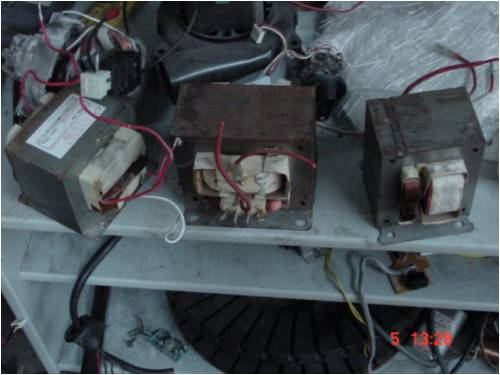
<It is not like microwave transformers are scarce, or not easily rewired to spec.
Where are you suggesting using re-wound microwave transformers?
oztules Guru Joined: 26/07/2007 Location: AustraliaPosts: 1686
Posted: 11:19am 26 Jun 2010
Copy link to clipboard
Print this post
in a word yes
like this:
and this:
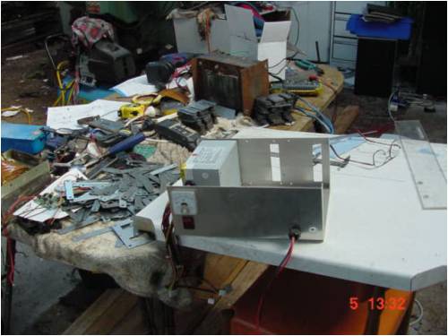
and using 2 lots of plates for a 1.5kw unit..... like this
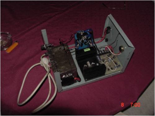
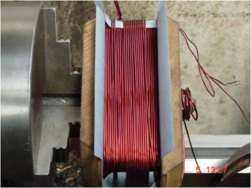
And here we are winding the primary for that big one. .... it's 1.8mm wire.
Those microwave transformers are the best thing I have come across for good laminates. Their original primary is no good for 240v operation, as it is designed for ferro resonance application (hence the shunt in between the windings). It is designed to run over saturated.... which translates to HOT.
So the windings are only good for spare wire. But the plates are great, and a lot of them use the same size stampings, so you can design your core for whatever cross section you want..... just keep adding plates until you get the square inches that you need to fit the windings in the window.
Strangely, for laminates that are welded together, the eddy currents are not too bad, although I like to separate them, and assemble them in the traditional manner. (the mess in the picture above)
The only exception to this is making low impedance transformers for electric fencing. There I just cut the transformers open at the weld, wind the new windings, and weld them back up. One 40 microsecond pulse per second or so, is not a duty cycle as far as I'm concerned, and they will run fully saturated in this application ..... so niceness is out..... I also use the secondary winding as a source of wire for winding the secondaries of the multivibrator transformer (ferrite core) that supplies the 700v to the primary of the main transformer in this instance
Yes, it will take 3 transformers for a 3 phase unit...
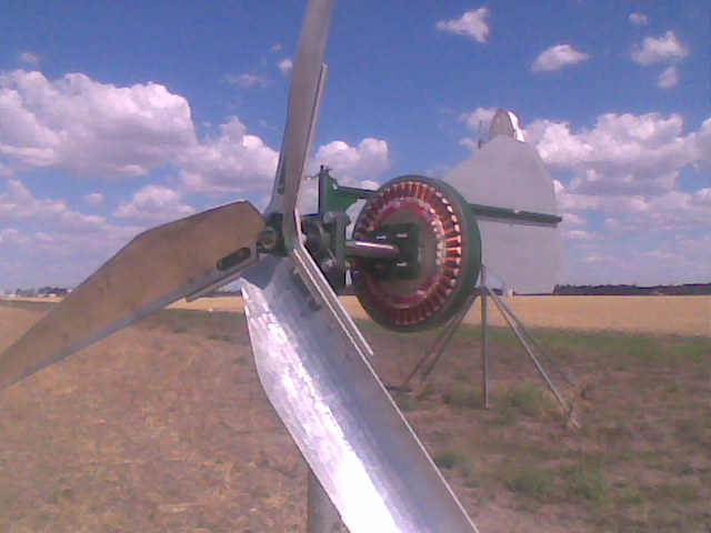
Here is the one off the AWP system.
................oztules
Edited by oztules 2010-06-27Village idiot...or... just another hack out of his depth
Page 1 of 2
Print this page
The Back Shed's forum code is written, and hosted, in Australia.