
|
|
Forum Index : Windmills : AX 300-3 & VLLR
| Author | Message | ||||
fillm Guru Joined: 10/02/2007 Location: AustraliaPosts: 730 |
Hi All, As I have been quiet over the past few months it has been for a few reasons , I think in one off my last posts I gave a link to some video I took on a fairly windy day showing my mills furling and the logging system. It did not stop there , well it did with both mills dead at the end of the day, it only started ... So you don't have to go back over and find it in with a site search Here's the LINK The list of events that happened later that day has lead me on a complete redesign and rethink on how I can control my mills. 1/ The wind continued to strengthen 2/ The Grid went down which took away 2.2kW of load 3/ Both mills were combining to output over 4kW in peaks 4/ 1kw dump load could not keep up, even with both mills furling as peaks still continued as the mills furled In the pressure of the moment as a lull came through I threw the shorting switche�s , the AX300-2 did not stop, but instantly went into an unloaded state and as the gusts came the blades were reaching RPMs that were sphincter clenching. The mill could not furl as gyroscopic force had taken over, and I could only watch on from a safe distance, and trust my engineering . The blades and hub handled what I would think was in excess of 1200RPM peaks at times. The sound from the blades resembled an aircraft doing propeller checks and a helicopter landing all at one time, anyway the blades and mill survived structurally . The smaller mill also burnt the stator and windings, but due to the iron core and shorted windings eventually it came into a stalled state. Below are a couple of pics of the destruction, but I do not want to dwell on it, or go into any lengthy debates on the �whys/what�s � and in depth of that. 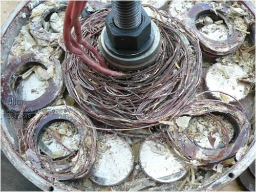
Ax300 Stator a bit worse for wear, smashed,chewed up, and bird nested . 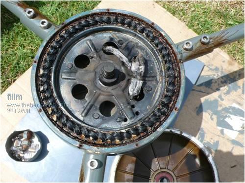
500W Kit Stator Cooked- High Temp Silicon wire is crispy. As This has now been my 2nd AX melt down / Blow up or whatever you want to call it, and also the 2nd 500W melt down, I needed to seriously reconsider how the mills are controlled in high wind situations. The options considered for rebuilding the mills, so this doesn't continue to happen on a regular basis, which seems to be every year at the same time. -Mechanical braking... eg Disc or band/drum brake -Better Furling -Mechanical assist furling -Diversion Load resistor braking .. -Combinations of all the Above -Piss the mills of and get my kicks from watching solar panels. 
The common denominator here is that the GOE222 Blades and the power that they develop in high wind , and the fact that once over a certain RPM mechanical furling becomes difficult , but in saying that the power they develop in light to moderate wind is well worth the trade off of having way to much power at the high wind speeds. This could be said with all blade profiles in strong wind, and burning up stators appears to be a fairly regular occurrence associated with the Axial Flux design, due to its resin encapsulated stators and the lack of heat dissipation. The problem I also Identified with both mills, being basically low resistance windings. The AX300 is wound for a 48V cut-in RPM of 200, and then uses a Cap/Doubler to bring the actual cut in down to 100rpm. This enables the alternator to achieve higher efficiency with less copper windings needed to get the low end power, which equates to less heat in the windings with the AX300. The 500W Kit @48v is a lot higher at 350RPM, and uses both a Cap/doubler and quadrupler in parallel to get a cut in of 130RPM. This has enabled the 500W mill kit (which better suites 24V) to now be used at 48V. But there is a downside to this. When the mills are shorted out to brake or stall the mills, the doublers are bypassed and causes the original wiring configuration to dissipate the heat generated from the power of blades, this means that when stalled using a shorting switch in high winds, the blade rpm can reach a point where a fair/large amount of power is being produced in stall which has to be dissipated as heat, due the GOE222 blade because of its high torque low RPM capability. With shorting the phases the energy is dissipated internally in the stator, (with some additional loss with line resistance) causes the coils to overheat and expand rapidly, which is not good for epoxy encapsulated windings. Another anomaly I picked up and is limited basically to this particular design of enclosed stator type AXFX, is that both times it has burnt a stator, the stator was forced in one direction towards the front magnets, I had not paid too much attention to this, but while I was assembling it for a clearance check I remembered that it have a slight misalignment of about 10mm with the magnet plates, that happened due to a bit of a mistake when I originally built it, for the last 40mm when the two plates are lowered together it required alignment rods to align the bolt holes, this really is no different than decogging for an AxFx and the flux lines are angled as they cut the coils. As Both Gordon and myself built these similar AXFX alternators 3 years ago it has always been a mystery to why mine was so quiet and barely makes any noise, as its quite common for AXFX designs to have a growl at cutin and while producing power. This then identified another problem I think could be happening, being as the stator gets warmer and more flexible the force of the angled flux lines constantly forces the stator in one direction, and eventually causing contact with the magnets, and more so when shorted or loaded heavily. Resulting in both burn outs having made contact to the same areas on the magnets 
Contact on front Mags I was going to re-align the holes so the flux lines are at 90deg to the windings to stop the flex under load but decided not to, and give the front air gap a little more clearance, as having a quiet generator is a good option, with the mill location being close to the house. My main problems have always been with controlling my mills in high wind, when no more power is required. ( probably in reality it is common with all mills ) All power generated is feed back to the Grid by 2 x 1200W Latronics PVE grid inverters that feed off a 48v 225A/Hr flooded Lead Acid Battery Bank. There is 2.3kw of solar feeding in to the batteries as well as the 2 Wind Generators, as the solar is only peaking for 4hrs a day, and allowing for losses with inverters etc. I only have a gap of 300 ~ 400w that the mills have during the peak solar period, I installed a 25 X 3000Farad Cap bank in parallel with the batteries to absorb wind gusts and solar bursts, as there is very little A/hr absorption in the Batteries as they are constantly held @ 52.3V due to the cut off point for the inverters. The Caps will absorb approx 8000W in 30sec, since they were added the spikes are slower and smoother. 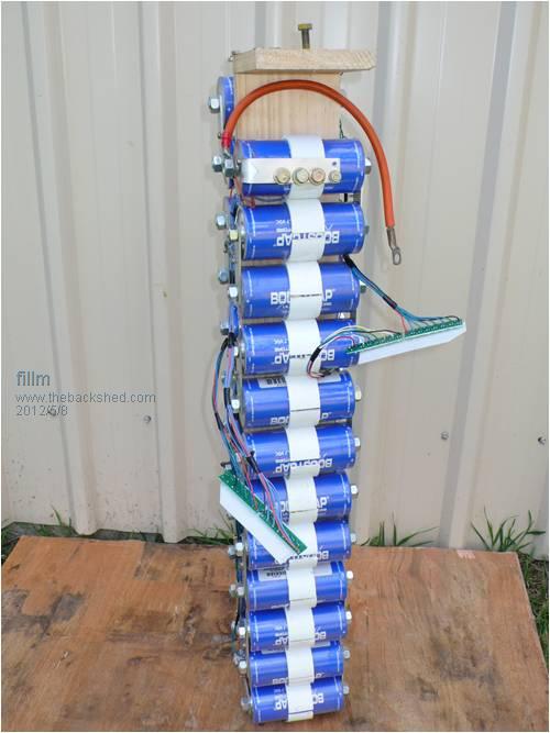
25 X 3000F 2.7V Ultra Caps In this situation it is very hard to size a dump load that dumps excess power from the batteries, so it is a better option to use a diversion load for the mills and use that to stop the power from the mills completely when the voltage is high, or the grid is down, or the inverters are lagging. The solar will regulate its self through the MPPT Charger, but if the wind is fairly blowing and the sun is shining (which only happens a few days a year in my poor wind location) this is the time when a good control system needs to be in place, and more so for my next Axial Ax400 (which is under construction) goes up, increasing the power to almost twice the output of the AX300. With all this to consider I have had an idea in the back of my mind, it has come from my present work place, where the machine I work on and operate uses a system called a "Liquid Start Resistor" to start Conveyor belts for a 12000TPH Crushing and Conveying system, that shifts overburden at the mine I work at. Each of the two main belts , one which is 2.5km have 4 x 1200kW motors that need to start slow at high torque and slowly ramp up to full speed of 5.8m/s , this is done by the Liquid Resistors that basically have two sets of annodes in a tank, basicly one set are moved closer to the other by a drive motor untill there is no resistance. The tank is filled with over 1000L of liquid with high Ph. Basically very salty water. When starting under load over 1 megawatt @ 1200V x 4 is being passed through each of the liquid resistors and excess power is dissipated into the fluid. These monsters have cooling pumps and fans and you only get 3 consecutive starts before having to go into a LRS cool down time out. Below are a couple of pics of these units and what is being started . 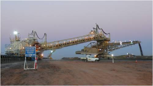
Spredder 
2.5Klm Conveyor 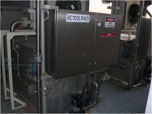
High Voltage liquid start Resistor So the thought I had was to use this concept but in reverse to control a windmill, buy dissapating the power into liquid when shuting down or controlling,instead of into the windings so I set up a bit of a test to see how well it would work, I did a bit of a video of the test to show the basic idea which was set up on my test stand. The Basic components and operation . -The Liquid load can directly connected to the Mill AC -Infinately variable through liquid concentration or plate immersion -The Anodes/plates are just S/S 1.5~2mm sheet cut to size -The liquid is a solution of rain water and Sodium Carbonate " Ph Increaser" for pools/spars , other options .. Bicarb, Caustic Soda, Acids, Salts���� The test shows only 3 plates with the 3 phases connected to them, this is only effectively acting on 2 phases a 4th plate is required to fully balance the 3 phase loading. Heres a link to a Vid I did of the doing a test LINK HERE As you can see in the Video, the load can be infinitely controlled by the amount of surface area of the plates in solution , as the plates are immersed in the liquid the AC load comes on, and the DC output drops and the generator output is then being dissipated into the liquid as heat. Also the Loading torque on the alternator is increased dramatically from what the load was at the set RPM as the plates are fully immersed, by having this type of diversion load it can be bought in smoothly and the loading increased to the point where the mill is stalled and stops producing power. I started to then think about how to put in a control mechanism to lower the plates into and out of the liquid, and of course the options here are limitless and I could go on and on with every option that went through my head, from water pressure to air pressure, magnetic and the list goes on............ From here on is where the whole project started to take on another direction, as I keep in contact with Pete " Downwind " and Gordon Gw@PE who haven't been active on the forum for quite some time, I explained to Pete my thoughts and tests that I had done so far with the Liquid Resistor, I also should say at this point, that this control system is nothing new , and the whole concept has been around for donkeys years, whether any one has gone down the same path as I am, I don't really know because haven't been able to find to much on the internet about Liquid Resistors as such in this application . As this is using AC it creates very little hydrogen, DC can do the same but creates a lot more hydrogen and will also get a deposit build up on one plate. Anyway after talking to Pete he also decided to set up a bit of a test to see what I had explained, and from what he observed agreed that the idea had merit. After my 2nd AX burn out we had been discussing ways to monitor stator temperature in axial flux alternators, and he had come up with a concept of using a infra red slip ring rather than wireless that would allow data to be sent around the yaw bearing using 3 infra red LEDs and one 38khz IR pick up sensor , this would not get affected by interference from the blades rotating or signal losses. With a DS18b20 temp sensor mounted in the stator, the data would then be recorded to my logging laptop to see what is going on with stator temp when the mill is hammering. 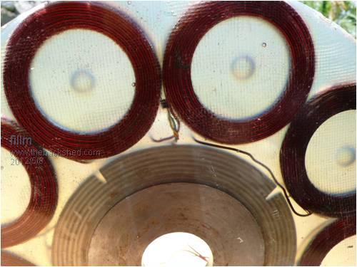
Sensor in stator At this point the whole concept started to take on a whole new direction as with Pete involved and his wealth of knowledge and experience with circuit design and programming Picaxe, we started talking about what could be done with options (conditions) that the liquid resistor would be activated by, and what would be best to drive the probes, as I stated prior there are a whole lot of different options here, but first we decided to try using a stepper motor to drive the plates in and out of the liquid with a threaded rod. The idea did work but lacked enough speed. I then sourced some fast acting linear actuators that could extend and retract 200mm in 1.25sec along with controller boards as well as a manual motor controller for testing , the only problem is the actuator voltage was 24V, so would have had to use a 48VDC-24VDc converter which luckily I have a few I picked up a few years back . After sending down a linear actuator and solid state motor control to Pete he then put together a control board and I started on all the fabrication of the tank and plates etc. 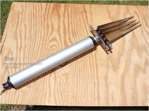
Linear Actuator with S/S Plates mounted 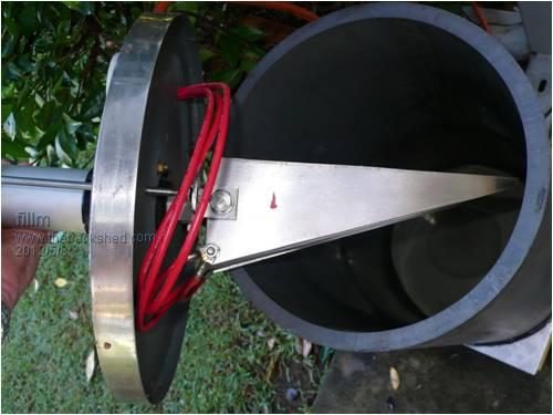
Tank made from 300mm ABS Pipe After probably much hair loss and probably a whole lot of cursing the whole system was tested and sent up to me to fit, and I must say as you can see from the pics Pete put together a very professional well finished control box that has all the circuitry which I mounted into the lower electrical box . 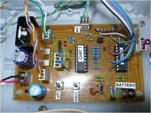
The controller triggers on... * 1-Voltage Max and min ( Adjustable in Program) * 2- Rpm - ( if over 340 Rpm Shutdown, if under 300 Rpm Restart ) Adjustable * 3- Stator Temp ( If Temp over 80DegC Shutdown & If Under 60DegC Restart) Adjustable * 4- Emergency Shutdown * 5- Manual over-ride for in and out The motor control board is also in the control box but not shown . 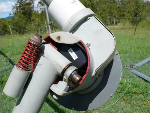
The infra red sender unit mounted into the nacell , and is powered directly from the mill AC . 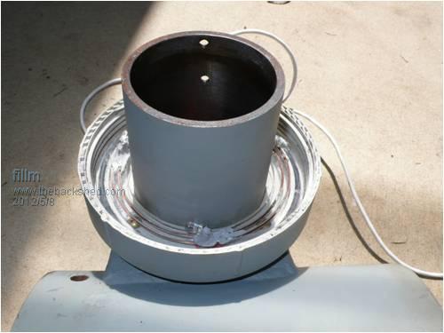
The 3 infra red senders are mounted in a 100mm pvc pipe cap and the joiner screws up and holds the ring in place and also shields the pick up from direct sun . 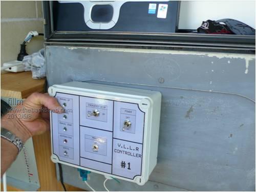
The "VLLR" (Variable Load Liquid Resistor)control box which is now mounted into the box front also has all the manual controlls for Emergency Shutdown / Stop and manual in and out . 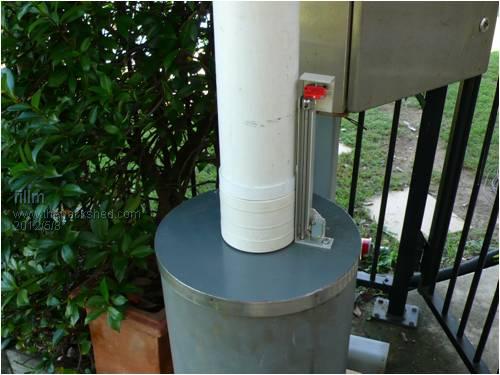
The finished unit with the upper and lower limit switches to tell the controller where the plates are , the actuator also is covered by some 100mm pvc pipe for weather protection . I had originally intended to mount the actuator on a S/S tank with the plates being rotated into and out of the fluid with the actuator connected to a suitable sized arm, as I had a heap of the large ABS pipe that was originally used for blades, I decided to go with a vertical arrangement as shown in the pic, it was simple to build but setting up the limit switches was a little tricky. I now think that it is a better concept to go back to my original plan of the rotating the plates with a purpose built S/S tank when the new Axial goes up . This is also where I think the whole concept moved a bit more hi tech, (well it actually happened way before this point but I will slot it in here.) I came across a program called �Team Viewer� and it enables access to computers connected to the net from anywhere, as well as from the latest Iphones and androids , basically I can log on to my Logging Laptop and check on the mills and solar from anywhere in Australia and I would think the world as long as you have internet access or phone service . 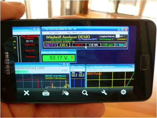
We basically thought it would be pretty cool to be able to control and shutdown the mill from thousands of miles away, Gordon put together a VB program with an on screen display and some activation buttons that would enable a shutdown and Restart as well as the ability to manually control the actuator. The on screen keys send serial data to the controlling circuit, which in turn implements the commands. The control circuit then sends information back that is displayed in a status window to show the instruction had been activated, it also records to a log record any info of what has been happening with temp and if it has shut down for any reason and the reason that triggered the shutdown. 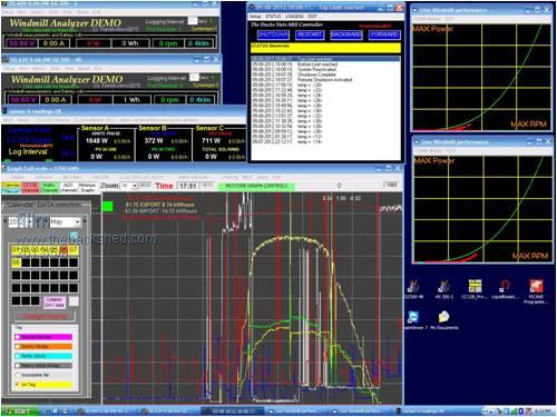
Its not a really clear screen Dump Pic but thats what happened today and its not much to rave about in the wind side . The VB program can be seen in centre with the stator temps recorded at 2 deg increments during the day and a shutdown and restart at the top of the status screen , so whatever is on that computer can be controlled from a laptop / home computer or mobile phone as shown above Anyway that�s about it , since installing it I have not had any real wind to rave about, but it has done its job quite a few times with the Grid going down and the solar pushing the battery voltage up past the shut down set point 59.5V, I did have one gusty day when high RPM activated the VLLR. It is also very interesting to watch what is happening with the stator temp, it is surprising how quickly temperature rises once it starts to produce over 500w, this is a bit of an eye opener and quickly jumped from ambient to 55deg a few times on a few 1kW + Bursts. At present the Temp is set to shut down at 80DegC and now just a waiting game for the winter winds to arrive and give the whole system a good work out and at that time I hope to get some more Video of the system working at protecting the AX300-3 and hopfully this year is not a -4 . I know this specific concept that has been put together as a team effort might not be everyones cup of tea, but there are other options, and could be simplified as a basic shutdown resistor and could even be used to capture excess power as stored heat with the use of a heat exchanger , the one trouble that does arise is with switching the low voltage AC with a SSR, and at present I have not found such a beast but it can still be done with conventional relay type AC rated types . Also there are many other options that could be used to actuate the plates into and out of the liquid. I have just obtained a couple of nice S/S tanks and will be re-designing the way the actuator and plates are mounted along with the new AX that is taking shape at present, but that will be another thread. PhillM ...Oz Wind Engineering..Wind Turbine Kits 500W - 5000W ~ F&P Dual Kits ~ GOE222Blades- Voltage Control Parts ------- Tower kits |
||||
| Gizmo Admin Group Joined: 05/06/2004 Location: AustraliaPosts: 5187 |
Good post Phill 
That axial made a real mess of itself. I think the liquid resistor is a good idea. The linear servo will give a fast response, and with the right brains in the controller, the load current can be adjusted quickly and precisely, not like the On/Off dump controllers we commonly use. It will be interesting to see how it performs when the winds pick up. Heat build up in the water may be a problem, but if you use a stainless tank it should be able to get rid of the heat, if not just weld on a few cooling fins and paint it black. Was thinking about ways to raise and lower the plates, knowing you and Pete did try a stepper motor driven thread but found it to slow. What about this below. 
The stepper motor, or maybe a RC servo, is mounted out on the side of the tank, and a direct drive shaft goes throught the tank to a bearing/bush at the other side. The 4 plates are attached to the shaft and shaped as shown. 90 degres of rotation will raise or lower the plates into the liquid, quickly. The picture shows the plates in 3 positions, from full down to nearly full up. If you have even seen the variable tuning capacitor in a old valve radio you will reconize the plate shape. A small counterweight could be added to balance if needed, and the only real resistance to movement will be wires conneted to the plates. A stepper motor would operate it from one end to the other within a fraction of a second, but I think you could also use a RC servo motor ( hobby, remote control ), the PicAxe chips have the commands to operate RC servo's, but they do jitter a bit. Glenn. The best time to plant a tree was twenty years ago, the second best time is right now. JAQ |
||||
| fillm Guru Joined: 10/02/2007 Location: AustraliaPosts: 730 |
Hi Glenn, Yea you are right ,there are a lot of options with plate design and how to control them . I like the plate design you have shown and I can remember those plates in the old valve radios . The only draw back I see is that it increases the size of the tank above the fluid to allow the plate to rotate up and clear which decreases the fluid volume or increases tank size. The same can be said with my present set up as the plates are 300mm long so they need that clearance, but it was an easy option to get it all up and going . In the next liquid resistor I intend to go with approx 30 x 400mm plates with a bit of a taper at the end . My tank is 500 H x 500 L x 300 W , so allowing about 70mm for the rotating shaft and a bit of clearance between the fluid and the bottom it should give a fair volume of liquid to heat, if required. To get more load can be easily done by raising the Ph , closing the plate gap or increasing the plate width . The most important thing is stalling the mill when no more power is needed and taking the heat that would have been generated in stopping the mill from the stator and dissapating it as heat in the fluid until the mill comes into stall, and when in stall also dissapating the current/power produced in that state as the mill will be still turning to the point where it stalls to the wind strength and blade power generated to the plate resistance in the fluid. The thing I do like with the liquid resistor it gives a very smooth shutdown. PhillM ...Oz Wind Engineering..Wind Turbine Kits 500W - 5000W ~ F&P Dual Kits ~ GOE222Blades- Voltage Control Parts ------- Tower kits |
||||
| brucedownunder2 Guru Joined: 14/09/2005 Location: AustraliaPosts: 1548 |
Bad news Phill,, Remember the silly old fart that suggested a disc brake years ago ?????.. It's still in a plastic box ,, bet you it will prove my point some time soon ... 
Don't mean to be rude ,,, but you did put me down on my suggestion!!! Bruce Bushboy |
||||
shawn Senior Member Joined: 30/03/2010 Location: New ZealandPosts: 210 |
Yes bad news but it may lead to better control for future mills, this I will watch with interest. I was away from home a fortnight ago and murphy sent me some 120k gusts mabe stronger? I got home just as it was all over my mill was still spinning I think it only lived because it furls early and im not getting even close to its top end power ability, it has started to moan when working even louder now and it needs rebalancing so its coming down for the first time as soon as I get time but yes I agree its hard to get the best from a mill and have it live these big wind events. |
||||
Downwind Guru Joined: 09/09/2009 Location: AustraliaPosts: 2333 |
One of the things i have done for some time now, and is a large part of the controller for Phill, is to use RPM limiting. I dont understand why this is not used more widely, as its only a matter of monitoring RPM and should a pre set speed be reached, then apply the brakes (dumpload), i dub it a "The mill saver". In high winds there is little point allowing the mill flog its guts out and reach close to runaway speeds, and think it is far better to hit the brakes and pull the mill speed down, then allow it to spin up again then repeat as required. This also allows for furling that is not 100% correct to be compensated by rpm limiting, as loading the mill heavy can also help pull it harder into furl, as well as it not reaching runaway speeds. There is no point in allowing it to reach high current outputs in strong wind/gusts, then trying to shut the mill down as this is where damage occurs, the extra bragging rights of the high power peaks that might be gained from high rpm adds little over all power to the daily total, and is far better to loose the absolute top speeds and save the mill to fly for another day. (broken mills make no power) With design and development testing i had done with Phill for the VLLR, on bench testing here at 24 volt it was able to control the voltage to the battery within less than 1 volt hysteresis. For example with 15 amp output, 10 amp could be sunk to the fluid and 5 amp supplied to the battery, maintaining a steady battery voltage, allowing for the battery to be full charged or topped off, as the voltage rise the probes would step in slightly shunting more current to the fluid and maintaining the set voltage. This made for what jokingly got called "The Ducks Nuts" controller as the principle of liquid resistors acting on the 3 phase AC worked so well and so smooth. From what i have seen thus far, the system Phill has constructed here is really "The Ducks Nuts" of control methods, but we both agree real world testing will prove this true or false with time, as bench testing can only prove concept and mother nature can pose issues that testing dont account for. Its a lot of work and depends greatly on electronics for control, so not a project for the light hearted amateur. The control electronics is split between 2 chips to keep response times fast and smooth. 1 chip controls the actuator and monitors the voltage using 16 bit ADC resolution via I2C. The second chip monitors all other inputs/outputs from limit switches, rpm, temp, serial data in and out from PC, manual switches and any other function, then controls chip 1 accordingly. Each function received to chip 1 is acknowledged back to the second chip to ensure the command has been received and executed, chip 2 then sends a text message to the PC to be logged in the records of operations preformed. Pete. Sometimes it just works |
||||
| fillm Guru Joined: 10/02/2007 Location: AustraliaPosts: 730 |
Hi Bruce, I think this is better placed over here , I find waiting a day before you hit the enter key helps  . .
I will be posting another thread about what I did to the little 500 Kit mill with manual overide furling, it might be of intrest to you . I think it would get to confusing when this dealing with the liquid resistor . Shawn.. Yes, bad news but its all done and dusted now, but does sounds like you might have something not right , the winds you are doing battle with over there are so destructive for windgens. You have hit the nail on the head , getting the best out of low to med wind bites you on the ass when the storms come and with the AXFX Design its very limited cooling it can all go wrong so quickly . Now having the stator temp logging it will give a good indication of temp rise and fall.... When my wind comes ... Pete , thanks for putting a bit more detail to the thread , should have called it the AX300-3 and "THE DUCKS NUTS" . PhillM ...Oz Wind Engineering..Wind Turbine Kits 500W - 5000W ~ F&P Dual Kits ~ GOE222Blades- Voltage Control Parts ------- Tower kits |
||||
| Downwind Guru Joined: 09/09/2009 Location: AustraliaPosts: 2333 |
[quote]should have called it the AX300-3 and "THE DUCKS NUTS" .[/quote] Phill, I only done the test tube conception it was your baby to give birth to, so you can call it what you want. Maybe the "Golden Goose" would be more fitting to how well it operates. Pete. Sometimes it just works |
||||
| fillm Guru Joined: 10/02/2007 Location: AustraliaPosts: 730 |
I had a bit of wind about a week ago that tested the "VLLR" liquid resistor control system out a little and also gave a good indication on how quickly AXFX type stators heat up when they are starting to pump out the watts . I would not call it a high wind day but in a period of about 6 min the stator temp went from 70deg up to 80deg with a few gusts at around 35 ~ 40klm . The data log can be be seen below for that period with the shut down for ( high RPM ) coming in at the gust peak and at the same time the High Temp shutdown activated @ 80DegC. Prior to this there were a few peaks of 1500 ~ 1600W, this being well below what this mill has peaked at previously. The Restart can be seen as "Top Limit Reached " as the plates come out of the fluid. 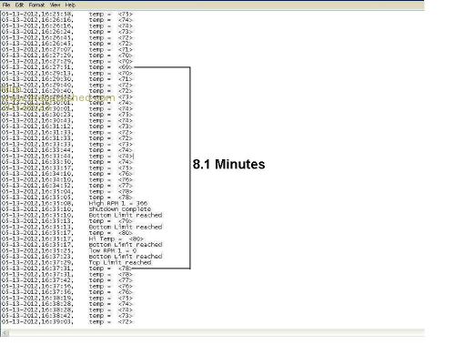
As the whole day text file is too long to fit on a screen dump I can only show sections of it, but for most of the day the temp sat around the 50~60deg in 15 to 20km wind. The pic below is a screen dump of the same period on the windmill data logging screen which shows the the peaks coming through for the same period on the VLLR status log file and being logged at 10sec intervals which does not capture the actual peaks, the shut down period and then re-start can be seen. 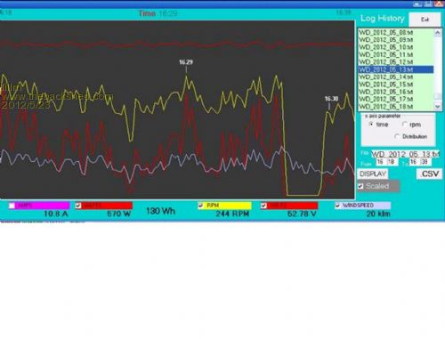
The gusts were definately not sustained , and what I find now with the ability to log what is going on with heat up at the mill head is a real eye opener . As the 80deg Temp set point shutdown has been a trial to see what it actually takes to get to that point and the fact that it really does not take high output for a long time to get to that point. With cooked stators being one of the most common failures for axial flux type alternators it is little wonder when you see this data . With the heat build up over a prolonged high output period causing the softening of the resins used in the stator combined with the forces trying to bend and move the copper windings, then it can all to quickly add up to a burn out and/or a run away mill as I have experienced 2 times now with this mill when a forced shutdown was required on top of prolonged high wind and output. All in all the Liquid Resistor Control system did its job in automaticly protecting the mill and smoothly stopping the mill when a set point was reached and held the blades in stall untill it was allowed to restart, the High temp set has now been raised to 95deg and the RPM left as is to see if that will keep the stator temp stable before raising the RPMs . I will also add that through all this the mill was still furling as it should in the gusts and even with the furling set quite soft the stator still heats up fairly quickly. PhillM ...Oz Wind Engineering..Wind Turbine Kits 500W - 5000W ~ F&P Dual Kits ~ GOE222Blades- Voltage Control Parts ------- Tower kits |
||||
| Octavio Newbie Joined: 20/05/2012 Location: MexicoPosts: 2 |
Hello everybody, I'm new to this forum, but I've been a reader for a long time. I usually hang out at the fieldlines forum. Very interesting setup film. Specially the possibility of being able to check on and control the mill from a mobile phone. I'm a bit of an android programmer myself (yet another hobby) and I'd be interested in writing up a program to communicate directly to the controller/computer. Cheers, Octavio Check my apps aFoil and aFoilSim on android market. |
||||
| fillm Guru Joined: 10/02/2007 Location: AustraliaPosts: 730 |
Hi Octavio, Thanks and good to see someone from fieldlines come over for a visit , these new android phones and some of the apps are amazing . Nice work on your blade simulator App but I am not sure what program you could add to this system ? I guess the controlling the mill by a mobile phone would be frouned upon by some but its a bit of fun and who knows what the future holds . PhillM ...Oz Wind Engineering..Wind Turbine Kits 500W - 5000W ~ F&P Dual Kits ~ GOE222Blades- Voltage Control Parts ------- Tower kits |
||||
| Octavio Newbie Joined: 20/05/2012 Location: MexicoPosts: 2 |
Thanks for your comments, I was thinking more in the direction of replacing the app you are currently using to access your computer-controller for a more compact-less data being transmitted trough your mobile connection-purpose made app sort of thing (configurable notification triggers, etc.). I hope I'm making sense here. Cheers, Octavio Check my apps aFoil and aFoilSim on android market. |
||||
| fillm Guru Joined: 10/02/2007 Location: AustraliaPosts: 730 |
Hi Octvio, Thanks again for your offer but I would think the program required to do what "Team Viewer" is doing would be quite lengthy and difficult program to write . The Host " logging laptop" can be accessed by anyone with the T/Viewer program on their laptop/mobile phone as long as they have the address and current password . The password can be instantly reset after thay have accessed the computer, as well the owner has an Admin Password to gain access at all times. The good thing about this is the screen stays live unlike " Remote Desktop " and multipul users can be logged into the host computer, and the computer functions as normal for all to see. The program/app can be set up in minutes without the need for a complicated set proceedure like "RDP"and it works straight away. This has been an invaluable tool when we were first iorning a few bugs out , as both Pete and Gordon could be logged in and able to watch, access picaxe chips and reprogram from thousands of miles away as the need arose. The "team viewer" program is availabe as a free trial version as long as it not used for comercial purposes, hopfully it stays that way as it is a very expensive program/app to buy. If you do want to contact me to discuss what you had in mind feel free to drop me an email phillm6@gmail.com . PhillM ...Oz Wind Engineering..Wind Turbine Kits 500W - 5000W ~ F&P Dual Kits ~ GOE222Blades- Voltage Control Parts ------- Tower kits |
||||
| fillm Guru Joined: 10/02/2007 Location: AustraliaPosts: 730 |
Just a bit of an update , I had some good wind a few days ago but still not up to what you would call high wind, with gusts coming through at about 35 to 45 klm which puts it into the 10 to 12m/s range where wind turbines should be in the self protection stage . The control system was at one stage frequently being activated by the high RPM set point of 350 RPM and by the time the plates were fully in and loading the mill the Rpms a few times went through 400Rpm if the mill was comming out of furl at the same time of the wind gust . It was also incredible to see the brute power the GOE222 blade produces as the blades a couple of times powered through for quite a while before going into stall. The stator temp was another shutdown that came into play , as the outputs were reaching up to the 1500w and peaking at 1850W with the RPM limit the stator temp was easily getting up to 80 to 90degC and when the RPM limit was reached a couple of times while the temp was at these levels the shut down would increase the stator temp by 8 to 10 deg and then go into the "high temp" cool down . As this was around 20min I shortened this by reseting and letting the mill go after a few minutes and by this time the temp each time had droped by 20deg back to the 70. This made it pretty easy to see how these blade can easily smoke an AXFX mill as I have done twice now by trying to stop it by shorting. So basicly the whole system had a fairly good work out and I have now increased the temp shut down point to 105deg and left the RPM the same . The more I see of the behaviour of the GOE222 blade the more respect I give it with the power it can develop and what controls are needed to tame it in high wind. The liquid resistor and controlls did their job. It opens up another way controlling large amounts of power generated with out the need for large relays and to be directly be connected to AC from the mill , how the plates are moved in and out is open to many variations and plate designs like Glenn has drawn on the previous page. PhillM ...Oz Wind Engineering..Wind Turbine Kits 500W - 5000W ~ F&P Dual Kits ~ GOE222Blades- Voltage Control Parts ------- Tower kits |
||||
| VK4AYQ Guru Joined: 02/12/2009 Location: AustraliaPosts: 2539 |
Hi Phill Great results from your testing it shows that that power regulation can be achieved without load stressing from shorted output. It also demonstrates the control by temperature to be real effective, it shows that the 222 blades are the best available for smaller mills due to their power grabbing at relatively slow RPM and huge torque possibilities. All the best Bob Foolin Around |
||||
yahoo2 Guru Joined: 05/04/2011 Location: AustraliaPosts: 1166 |
I remember seeing a discussion on Fieldlines about controlling the blade pitch on a turbine with a linear actuator. The idea was pounded as not practical as the actuator would not keep up with the gusty nature of the wind. I thought the idea was very sound, the pitch was set in, say, ten steps in response to rpm and wind speed and maybe even power use. Ranging from optimum pitch through to parked. The intention was to have the actuator move instantly up the steps towards shutdown but a delay of a 5 - 20 seconds or even more as the wind gets stronger in moving the other way. Gusts of wind don't come out of nowhere so the blades would be partially shut down on a day that is likely to produce high wind gusts. That would mean that the actuator would only have to move a few more steps to handle a gust which it could do quite quickly. I think they proposed using a picaxe to do the job. This could perhaps be a refinement for your actuator that dunks the plates into the fluid in the future. I like the idea of a 2 or 3 step load with some hysteresis built in. I think the concept could be used in a number of applications. I'm confused, no wait... maybe I'm not... |
||||
| fillm Guru Joined: 10/02/2007 Location: AustraliaPosts: 730 |
Hi Yahoo Yea , that was the "active pitch control" thread , I thought the system had merit as well, but as soon as you seem to go off the beaten track its like sailing of the edge of the world for some of the purists out there. I like the idea of pitch control especially with the GOE222 blade because difficulty in controlling to much power in high wind opposed to tapered blades which can be stalled fairly easily , if pitch control was going to be used with linear actuators and micros then I would think the system somehow would need to be a defaulted to shutdown position if power was lost. The more experience I have with Axials and these blades in strong wind the more I lean towards pitch control, after seeing the fly weight mechanical system Royal Fabrication put together for his 20ft turbine the more I think he is on the right track and I am now thinking of marring the Liquid Resistor and mechanical Pitch Control with the new AXFX I am building to see how it goes. PhillM ...Oz Wind Engineering..Wind Turbine Kits 500W - 5000W ~ F&P Dual Kits ~ GOE222Blades- Voltage Control Parts ------- Tower kits |
||||
| BenandAmber Guru Joined: 16/02/2019 Location: United StatesPosts: 961 |
This question is to anyone that would like to answer it when winding the coils for a windmill instead of using round wire could someone use the flat wide wire and if so what would the be the effects of doing so it would be one flat wide wire that is wide not wire side by side hope everybody understands what I'm saying be warned i am good parrot but Dumber than a box of rocks |
||||
| The Back Shed's forum code is written, and hosted, in Australia. | © JAQ Software 2026 |
