|
|
Forum Index : Windmills : OZeTrade’s F&P VAWT Concept
| Author | Message | ||||
Chris Senior Member Joined: 12/09/2005 Location: AustraliaPosts: 146 |
Gday ozetrade If you have a look here http://www.oatleyelectronics.com/kits/Notes/k220.pdf Alot of your questions are answered. The two parts on the PCB that arent soldered to that say "Link for 12v use" are if you use a 12v windgen system then you put a wirelink between these two terminals. If you use 24v then leave nothing there. The six connections are: The left most and right most are the windgenerator input Positive and negative inputs. The 4 connections in the middle of them are for you dummy loads that you connect up. These prevent your battery from overcharging once it reaches a set voltage the power is sent into there rather then the battery. The wind generator and the battery as far as i can tell are connected in series with the positive terminal. Im not 100% certain of that, but im pretty sure thats how it works. Wait for Gizmo to verify that. The adjustment on the board is for setting what voltage your dummy load cuts in at i think (or when your battery is charged)... Not to sure though. Other then that your soldering looks pretty neat, nice work. |
||||
| Gizmo Admin Group Joined: 05/06/2004 Location: AustraliaPosts: 5116 |
Thanks for helping out there Chris, I dont get much time to answer questions and its good to know I have a few regular visitors who can help others. Just adding, the extra holes in the PCB are there to suit different shaped pots. The one you got with the kit used the outer hole, but a smalled pot would use the other holes. You soldering looks pretty good! But I dont think that bit of fluff was meant to be there, did it come with the kit? The best time to plant a tree was twenty years ago, the second best time is right now. JAQ |
||||
| Gizmo Admin Group Joined: 05/06/2004 Location: AustraliaPosts: 5116 |
Oops, forgot to add... The regulator works by monitoring the battery voltage. When the voltage gets too high, it connects the dummy load across the battery to drain off some of the excess power. So the windmill is connected across the battery, and charges it. When the voltage gets to high, the regulator uses its mosfets to connect the dummy load across the battery, thus draining off some of the battery/windmill power. Glenn The best time to plant a tree was twenty years ago, the second best time is right now. JAQ |
||||
ozetrade Regular Member Joined: 15/10/2005 Location: AustraliaPosts: 59 |
Thanks Glenn, Just need to confirm a couple of things:
Connect a bridge at the "Link for 12v use" to use board foe 12v. Have I got it right? Greg Just North of Brisbane in Redcliffe OZeTrade.net |
||||
| Chris Senior Member Joined: 12/09/2005 Location: AustraliaPosts: 146 |
Oh so thats how its connected... Thats a pretty good idea when you think about it. Nice and simple... |
||||
| ozetrade Regular Member Joined: 15/10/2005 Location: AustraliaPosts: 59 |
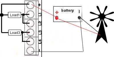
I'm having trouble following U guys...sorry. As it stands, the image is my understanding of what your saying.
....am I close? The Shunt regulator I have monitors the battery for full charge. When it detects full charge it dumps the load by placing a load on the battery - dump load needs to be at least same capacity as the power the gennie is capable of producing. The regulator also monitors battery for low voltage and turns off the shunt load so battery can recharge. Greg Just North of Brisbane in Redcliffe OZeTrade.net |
||||
| Gizmo Admin Group Joined: 05/06/2004 Location: AustraliaPosts: 5116 |
Almost.
Connect it like this if you had 4 load's.
And like this for 2. All the outputs L1 to L4 can be connected together if you have just one load resistor. The other side of the load resistors is connected to the +ve terminal. Glenn The best time to plant a tree was twenty years ago, the second best time is right now. JAQ |
||||
| Gizmo Admin Group Joined: 05/06/2004 Location: AustraliaPosts: 5116 |
That 2nd picture, the bottom load should have read "Load2" not "Load3", just to confuse ya. The best time to plant a tree was twenty years ago, the second best time is right now. JAQ |
||||
| ozetrade Regular Member Joined: 15/10/2005 Location: AustraliaPosts: 59 |
Hey I can actually follow that! Thanks Glenn. The concept of connecting directly to the battery was really throwing me - all other regulators I'd looked at, the gen power went into the reg first. Greg Just North of Brisbane in Redcliffe OZeTrade.net |
||||
| MrBungle Newbie Joined: 07/10/2005 Location: AustraliaPosts: 34 |
Greg, make sure the load is big enough to be able to dissipate the full power of the mill. The Oatley instructions probably tell you that already, but just incase... If anyone's interested, a similar shunt regulator was published in the Jan '94 issue of Silicon Chip magazine. Yer local library might have this mag. I vaguelly remember there was another one published since then that used kettle elements as the load(its probably normal is it?), if anyone wants to know month/year I can search through my stack of mags for ya. Simo |
||||
| The Back Shed's forum code is written, and hosted, in Australia. | © JAQ Software 2025 |


 If I'm understanding this correctly, the Windmill DC current is connected directly to the battery. The battery can cope with this because it is self regulating.