|
|
Forum Index : Windmills : TMA’s vertical axis wind turbine
| Author | Message | ||||
ozetrade Regular Member Joined: 15/10/2005 Location: AustraliaPosts: 59 |
Hi peoples, I almost over looked one of the comments made by Wayne in a topic I started. He left a link to company that has patented a vertical axis wind turbine that claims 40% + efficiency. I've had a look at their prototype image, and I can see some real potential, but it looks to me that it must be positioned just right to take advantage of the prevailing winds. The website is a real interesting read - as far as their claimed gains in efficiency. Any thoughts on this one? TMA article - If that bombs out: http://www.opensourceenergy.org
Greg Just North of Brisbane in Redcliffe OZeTrade.net |
||||
| Peter T. Newbie Joined: 24/12/2005 Location: AustraliaPosts: 1 |
My first post! after recent addition to wind power.... You might want to look up their later patents for some improvements in their design...... old design: http://patft.uspto.gov/netacgi/nph-Parser?Sect1=PTO 1&Sect2=HITOFF&d=PALL&p=1&u=/netahtml/srchnu m.htm&r=1&f=G&l=50&s1=6,015,258.WKU.&OS= PN/6,015,258&RS=PN/6,015,258 new design: No 20050204712 http://appft1.uspto.gov/netacgi/nph-Parser?Sect1=PTO2& Sect2=HITOFF&u=%2Fnetahtml%2FPTO%2Fsearch-adv.html&r =1&f=G&l=50&d=PG01&p=1&S1=%28taylor.IN.+ AND+wind.AB.%29&OS=in/taylor+and+abst/wind&RS=(IN/ta ylor+AND+ABST/wind) PDF copies can be downloaded for free from free.patentfetcher.com by just putting in the number.... I have also thought of a few improvments to the design. Please post update if you go down this path.... Peter T. |
||||
F&P murray Newbie Joined: 25/10/2005 Location: AustriaPosts: 22 |
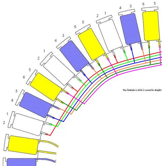
Hi Greg (ozetrade) Recently you replied on this forum re delta wiring of an F & P i have just done a scetch of what i think you said, but not sure which wiring is correct top or bottom
Bob Bob from Murray Bridge, SA |
||||
| ozetrade Regular Member Joined: 15/10/2005 Location: AustraliaPosts: 59 |
Not quiet right - try this
Greg Just North of Brisbane in Redcliffe OZeTrade.net |
||||
| KiwiJohn Guru Joined: 01/12/2005 Location: New ZealandPosts: 691 |
Greg, that looks to me like each phase is 14 coils in parallel, does that produce a useful volage at moderate revs? I understood the practical configuration was each phase wired to be seven paralled pairs of series connected coils?
|
||||
| F&P murray Newbie Joined: 25/10/2005 Location: AustriaPosts: 22 |
Greg thanks for the info on delta wiring, i tried the stator unchanged straight out of the washing machine on the bench with my new 900mm ply prop and it was putting out 58 volts rectified to DC just with a light handturn, if up on the pole at Murray Bridge at 13 metres high in a strong wind i could see 500 volts plus AC and dont know if i can rectify that sort of voltage to DC let alone get good amperage. I know that there are a lot of different ways of rewiring an F & P stator based on available wind and prop size etc but the wind here is abnormal and strong to very strong most of the time, i have a 2000+ amp hour battery set up in the shed and run all my 55 watt gimble lights a 12 volt water pump for the solarhart and have a 600 watt inverter for the TV/radio etc, i will be buying a large inverter soon as i am about to start building my retirement house and want it to be fully self sufficient apart from gas cooking. I thought i would need 3 windmills running to power the house and feel probably 2 in delta and 1 in star would do the trick but this may be too much, time will tell. Another problem i have overcome on the drawing board is how to heat the water and maintain that heat in my 8 person out door spa, i found the guy who replaces solarharts and have bought 10 complete solar panels off him for $10 each and 2 solarhart jackets for $20 each. I removed the heating element from one jacket and cleaned the unit right out, resealed the jacket and put it on my shed roof, i repaired 2 of the panels that were only rust damaged and connected it all up, use a12 volt pump to push rain water into the solarhart and presto free hot water! I then got to thinking about the spa and deciced 4 panels set 1265 mm below the spa towards the sun built in to my verandah will produce more than enough hot water to maintain the water at 36 degrees c simply by hot water rising in to the spa, no need for a jacket and i will put a thermal blanket over it as well. Bob from Murray Bridge, SA |
||||
| ozetrade Regular Member Joined: 15/10/2005 Location: AustraliaPosts: 59 |
Actually Bob, John is right. What I have described is a parallel circuit - but the term "delta" is referring to a parallel circuit, there are several ways to configure a parallel circuit. The method I described starts producing current at around 450rpm, 600+rpm before you start getting a useful current - 600W @ 800rpm for and 80series. Another method is much simpler and starts giving a useful voltage at around 300rpm up to around 500W @ 1000rpm. The method is:
However, the method that Glenn gives for rewiring star/delta is probably the most practical and versatile an efficient. His method can take adavantage of a star/delta switch that switches between the to modes. This way you can take advantage of low rpm to produce power in star mode, then auto switch to delta for high rpm efficeincy. Basically, if your expect to operate at low rpm most of the time, you should choose a star circuit. If you expect to have high rpm available to you most of the time, choose a delta/parallel circuit. Greg Just North of Brisbane in Redcliffe OZeTrade.net |
||||
| KiwiJohn Guru Joined: 01/12/2005 Location: New ZealandPosts: 691 |
Bob, of course you can rectify 500 volts but you are getting deep into the realms of sudden death for the unwary! I say this because any practical rectification scheme involves the use of capacitors and capacitors are stored energy. If you could bring the three wires down from the alternator to ground level it may be practical to use transformers to drop that to a useful voltage. Whatever ratio you divide the volts by the amps, potentially, go up by the same ratio. Using high voltage AC leads from the tower saves you in resistance losses too as resistence loss is related to current (i.e. amps).
I dont know what RPM you would be dealing with to get your 500 volts but pretty high I expect. High RPM means high frequency (i.e. Hertz, cycles per second). Most mains transformers you will come across are designed for 50Hz except US and other countries which are designed for 60Hz. As a general rule low frequency is very bad for transformers because they get hot instead of doing their job. So although an increase in frequency may be a good thing increasing it as much as you would may be too much for 'standard' transformers, something I dont really know. My only F&P rig is on a bicycle which produces 100 volts rectified DC from an un-modified stator wired in star configuration. This is with two stages of chain gearing and spinning at 430 RPM. I worked out the speed by measuring the frequency, which is 200Hertz and counting the magnet poles in the rotor (28 pairs). If I remove the rectifier and put a 230/32 volt transformer across one phase I can light two 50 watts 12 volt light bulbs. 100 watts at 12 or so volts! From my experiments I tend to believe that the modification of the stator is not necessary and may even be counter productive if suitable transformers are available. For a full system you need three transformers. I would have to think some more on the subject before I could positively recommend transformers rather then stator modifications but I do think it is at least worth considering especially if the leads from the generator to the battery charging position are long.
|
||||
| Gizmo Admin Group Joined: 05/06/2004 Location: AustraliaPosts: 5019 |
Hi all. First up, Bob I asume you have seen this page - http://www.thebackshed.com/Windmill/FPRewire.asp It covers connecting the F&P in star and delta. It means there are 6 output wires to deal with, and it could be done easier, but it gives the basic idea. As a rule, star gives more volts, less current, delta gives less voltage, more current. I can see why you want to try delta with your high winds. I live in a low wind location, so I've never tried to wire the stator as delta. Its one of those things where you need to sit down with some blank paper and a pencil, then play connect the dots until its right. KiwiJohn is right about the problems with using a unmodified stator and step down transformers, its not very efficient, and there is a safety risk with those high voltages. Just adding my little bit, the F&P can generate over 800 volts if spun fast enough. Normal 240v wire insulation is rated to 1000 volts, but a tiny pin hole or crack in the insulation will cause a flash over. These voltages are lethal, a F&P can produce enough power to easily kill you. Also the insulation in most 240v transformers is rated at 500v max, so these will quickly fail. So for these reasons its best to rewire the stator to a safe working voltage. I would rather have a couple of expensive thick wires running from the windmill to the shed, feeding a harmless 14+ volts, than a thin 240v lead feeding 500+ volts. Especially with the way I tend to run over these things with the mower! Glenn The best time to plant a tree was twenty years ago, the second best time is right now. JAQ |
||||
| KiwiJohn Guru Joined: 01/12/2005 Location: New ZealandPosts: 691 |
Glenn, good points (all of them). However, (fool that I am) I intend to do more experimenting with transformers as I have a project in mind that requires various voltages not easily produced by stator modification alone. If I can interest the right person I will try to drive some WWII military radio transmitter/receivers a la Rev John Flynne! Except we would be trying on the ham bands with maybe ten times the power output of those old Flying Doctor radios. In my case with the bike mechanism I feel I am never likely to see those 800 volts from the F&P unless Lance Armstrong comes to visit! In fact the voltages I get from this particular F&P seem low as I only see 100volts at 400 RPM. Perhaps I should investigate further. The wires are 0.8mm and the rotor is the individual magnet variety in white plastic, I have other rotors with the combined magnets in gray plastic. AaaaaH, it is all good fun but I really should be getting the house ready for a coat of paint to go on when the temperatures drop a little.
|
||||
solarmike Newbie Joined: 14/11/2005 Location: CanadaPosts: 26 |
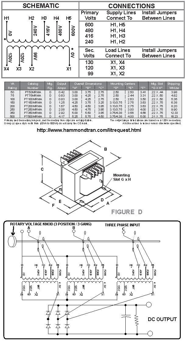
I am interested. You could use three small high voltage stepdown transformers that have multiple voltage taps and connect them up to a rotary position three gang switch and rectifiy their output through a six diode bridge and filter it with a capacitor and a 47K ohm discharge resistor. This will allow you to experiment with various voltages. Cation: if you select the low voltage position There will be a lethal voltage on the higher input taps. Be very carful. Good luck!
I am solarmike |
||||