
|
|
Forum Index : Electronics : Another Inverter Build
| Author | Message | ||||
Revlac Guru Joined: 31/12/2016 Location: AustraliaPosts: 1281 |
Hi Bryan, There's loads of Eastern Brown's and Black snakes here, just the other day there was a large Brown took off (as I walked past) in the same place I'm standing taking the photo of that carpet snake, the brown ended up going underneath the CNC Laser cutter, we just have be careful and be sure that the Doors are closed properly or they get in the house, a few have black snakes and pythons have and are not fun to try and catch them inside, It sounds like a DIY project!  lots of funnel web spiders too. lots of funnel web spiders too.Cheers Aaron Off The Grid |
||||
| Revlac Guru Joined: 31/12/2016 Location: AustraliaPosts: 1281 |
Well this morning got interesting, doing the usual stuff and then heard a POP, didn't know were from, whet looking then there was a crackle the fizzle and a few more pops, by this time I was around near the inverter and I saw the low output restart inverter on the screen, I though that sounded like mosfets popping.  Quickly shut off all the power to the inverter, Realising the inverter had all ready had shut off and waiting for me to reset, cant be too serious. Opened the inverter box and smoke come out, had the camera and a short video but not great, then could see the smoke at the top right above the output filters, (stink's horrible) could see the head of a Gecko that should not be there......  F F  it. it.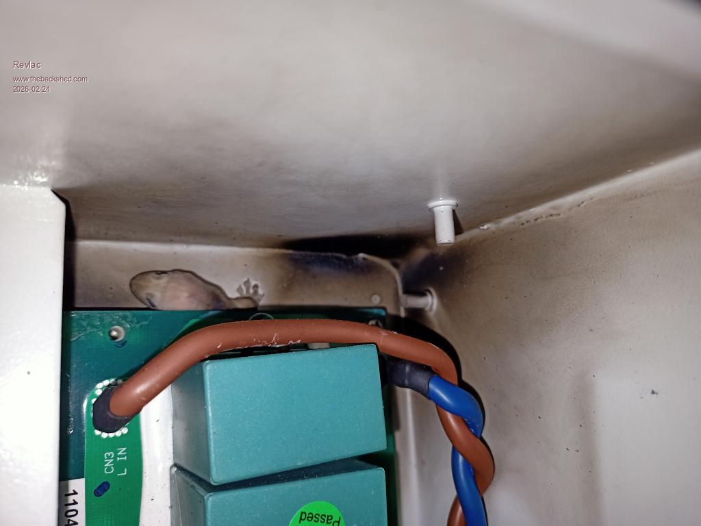 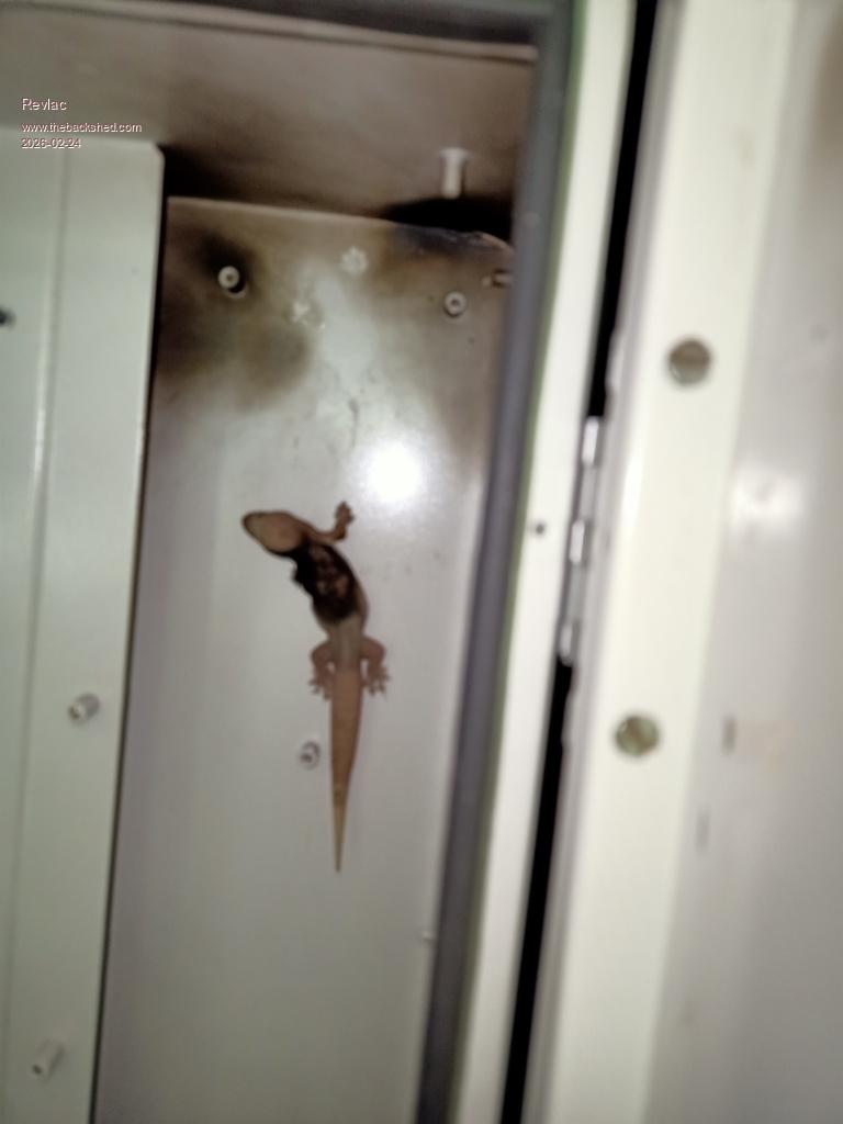 Should I leave its paw prints there as a reminder? 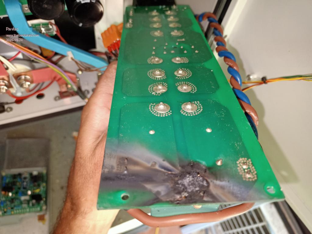 Burnt all the way through the PCB. 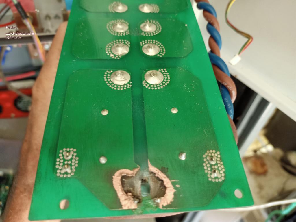 Cleaned it all up, give it a conformal coating, let it dry a little put it all together again and the inverter is up and running   , the loads that were on the inverter were shifted to the other inverter, took less than a minuet to do that. , the loads that were on the inverter were shifted to the other inverter, took less than a minuet to do that. So I Have some more work sealing up any holes to stop the little (and other) f getting in.Seems to be running just great. 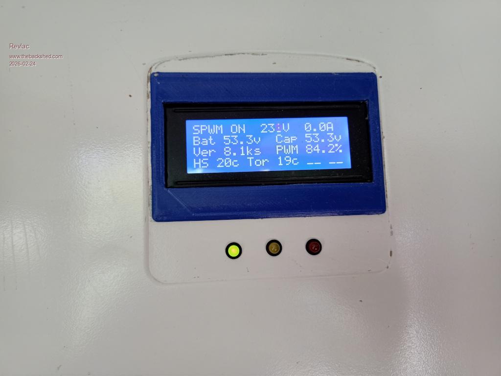 Edited 2026-02-24 10:58 by Revlac Cheers Aaron Off The Grid |
||||
| KeepIS Guru Joined: 13/10/2014 Location: AustraliaPosts: 2184 |
Dam!, I have 8 x 60mm air flow exhaust holes in the lower cabinet, already lost an Air-Con to the dam pests a few years back, I'd better get some mesh and block them, sigh! Lucky it was across the Caps. NANO:Inverter V 8.2ks - Linux AvrDude GUI script V4.1 |
||||
| Godoh Guru Joined: 26/09/2020 Location: AustraliaPosts: 668 |
Animals getting into electronics can be a big problem. I use 5mm square mouse mesh over ventilation holes and fly wire too. Had a few things that I have repaired over the years where animals got in and destroyed inverters and battery chargers. Glad your inverter was easier to repair than the Gecko. Nice easy fix for you Aaron. |
||||
| Revlac Guru Joined: 31/12/2016 Location: AustraliaPosts: 1281 |
Last winter we had -5c down the back yard and it was much better at the house but checked the battery Temp (these are outside with minimal insulation) and it was a bit low so I reach in and check the temp sensor was still attached to the battery..........CLUNK....WTF!? Inverter shut off from over voltage and the charge controller backed off from over voltage....ok, now check the BMS its reading -40c....(charge and discharge are both off at these temps) short story is the temp sensor wasn't plugged in properly and cant be pushed fully home into the (Daly BMS) socket by hand like the early models, had to use a narrow non metallic probe to push it all the way home.  To get to the point, the Inverter and Charge controller Survived the battery disconnect without any problems even when running some loads.... So regardless of battery type it should survive a knocked out breaker or main switched turned off by mistake, eg wrong shut down order. Not sure I would encourage doing this for a test but happy it all still works. Edited 2026-06-19 15:11 by Revlac Cheers Aaron Off The Grid |
||||
| nickskethisniks Guru Joined: 17/10/2017 Location: BelgiumPosts: 481 |
Glad nothing bad happened! I once had only a mosfet array disconnect for disconnecting my batteries from the system. Solar panels were just connected to a busbar without controller, only a dumpload (hotwatertank). System overvolted because of the hotwatertank was at temp, and voltage rised to 80V because allmost no load, but the ozzinverter just stayed working at that voltage the whole afternoon. Since then I try not to make stupid mistakes (bad/stupid design)and a lot has changed to the system to make it safer and robust. Edited 2026-06-19 17:00 by nickskethisniks |
||||
| KeepIS Guru Joined: 13/10/2014 Location: AustraliaPosts: 2184 |
That's nice to hear, I tried to catch-out the Inverter OV trip many times during testing, but it disabled the KiloVac every single time, also nice to hear the Charge controllers were fine as well. I'm just getting bits together to finally make some of the charge controllers. NANO:Inverter V 8.2ks - Linux AvrDude GUI script V4.1 |
||||
| The Back Shed's forum code is written, and hosted, in Australia. | © JAQ Software 2026 |
