Notice. New forum software under development. It's going to miss a few functions and look a bit ugly for a while, but I'm working on it full time now as the old forum was too unstable. Couple days, all good. If you notice any issues, please contact me.
Solar Mike Guru Joined: 08/02/2015 Location: New ZealandPosts: 1206
Posted: 09:54am 12 Mar 2025
Copy link to clipboard
Print this post
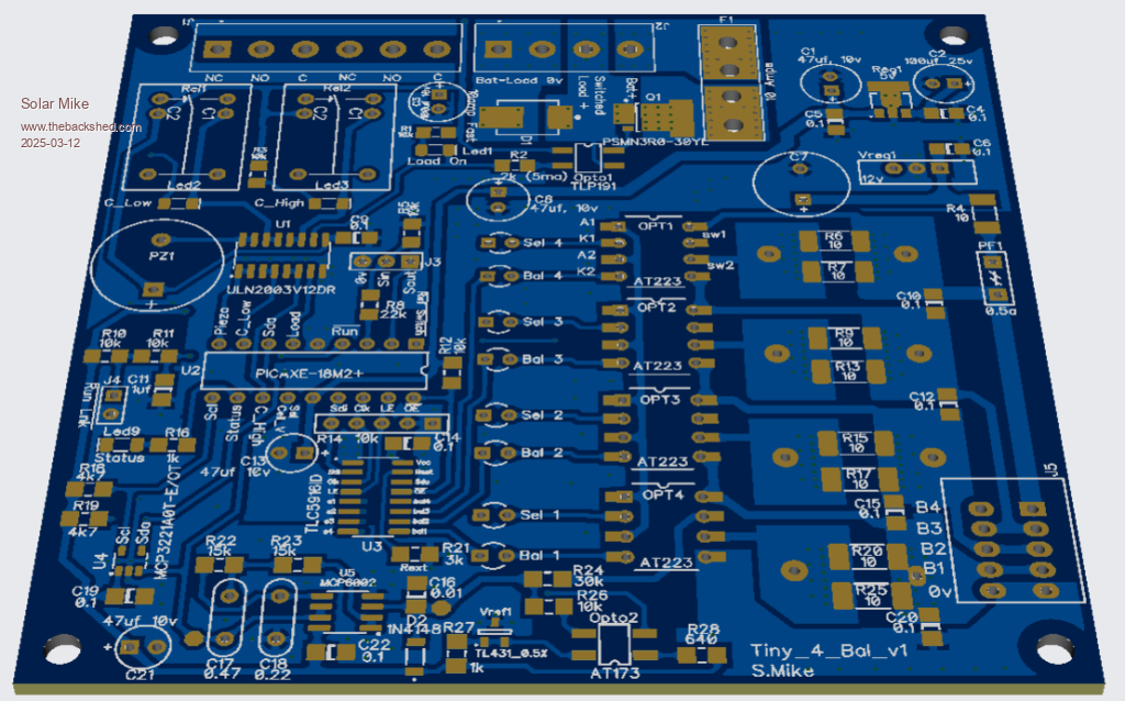
I have some small 4 cell 10-20 AH batteries (4s - 12V) out in the field and require a simple BMS to keep them in tune, there are inexpensive off the shelf products available, but I prefer something I can fix if there is ever a problem, so DIY it is.
This simple design uses inexpensive high current opto mos switches to both sense the cell voltages using a resistive divider and to apply a small 350 - 700mA resistive load for cell balancing. These switches have a 1.5A current rating and a very low on resistance. Serial first 4 bits select cell voltages, remainder select the load resistors.
An 8-bit serial constant current led driver is used to address the mos switches as required. A single mos switch coupled to a TL431 acts as a reference for calibration.
Voltages are measured with an MCP3221 12bit I2c A\D.
Two isolated relays used for over\under voltage output, a high current high side mosfet is used to switch the battery load (up to 10 amps) or turn on a large DC contactor relay when voltages are in limits.
Will get a board made up, test and report back here with a circuit and software.
PCB is 100 x 97mm
Cheers Mike
Revlac Guru Joined: 31/12/2016 Location: AustraliaPosts: 1265
Posted: 02:22am 13 Mar 2025
Copy link to clipboard
Print this post
AT223 photo relay, looks good. Cheers Aaron Off The Grid
Solar Mike Guru Joined: 08/02/2015 Location: New ZealandPosts: 1206
Posted: 02:45am 19 Apr 2025
Copy link to clipboard
Print this post
Update: I have this board working, testing it on some worn out 15 year 50 AH Lifepo4 cells, some slightly bloated, and down to 40% capacity, so they are all over the place; however they make great 12v batteries for powering field electronics from small PV panels.
I set the charger end point voltage to 3.5v and the balance voltage to 3.52v per cell.
Grabbing 4 series cells with no prior top balancing and using 2 x 10r smd 2w resistors in parallel as the balance load for each cell, things get very hot 80°c, as the balancing time is maybe an hour or so, allowing temperatures to rise.
Using larger through hole resistors mounted above the pcb works fine with the approx 700mA balance currents. The optimos relay chips are rated to approx double this current and get slightly warm, so they are ok.
Once the cells were balanced, loading them up with several AH of discharge, then repeating the process, worked much quicker, all cells being within a few mV of each other. This was using the CPU's internal 10bit adc.
I havent been able to test using the I2C adc chips as my order from Element14, somehow went via the USA and has been impounded by US customs with no release date, blame the orange idiot for that. Element14 are taking their time in sending me replacements
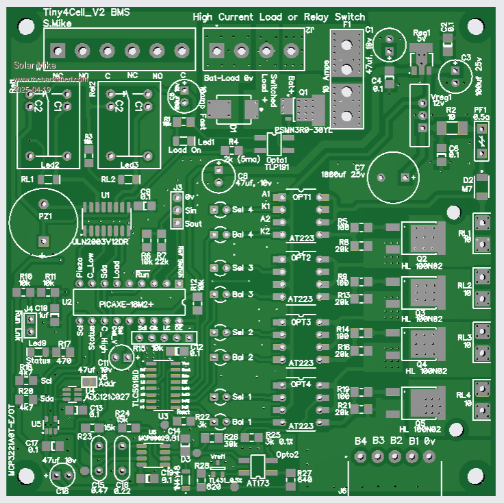
The design would work better for these larger cells if the load resistors were mounted externally an a small heatsink, even better, would have the balance currents increased to several amps. To that end I have altered the pcb some what to have low RDson mosfets driving the loads, the optimos switches now power the gates rather than the full load, the HL100N2 mosfets wont even get warm and work down to 2.5v gate drive.
Here is the new pcb, sending off today, same size 100 x 100mm