
|
|
Forum Index : Electronics : [Help Needed] DC Noise Affecting Arduino – SPWM Inverter
| Author | Message | ||||
| jony787 Newbie Joined: 07/01/2025 Location: Puerto RicoPosts: 7 |
Hi everyone, I'm working on a custom Arduino-based inverter project that generates a 20 kHz carrier / 60 Hz fundamental complementary unipolar SPWM—same output style as the EG8010. I'm experiencing severe DC-side noise that’s affecting: Arduino Nano Every (ATmega4809) analog readings Serial communication (UART glitches and resets) AC input feedback from sensors like ZMPT101B and WCS1700 System Details: Inverter runs off a 36V–50V DC supply SPWM generated by Arduino Nano Every (60 Hz fundamental + 20 kHz complementary carrier) DC rail has 4 × 10,000 µF bulk caps (PowerJack power board) 5V line originally from LM7805, now from LM2596 buck converter Arduino controls H-bridge and senses AC output via voltage/current sensors Images: 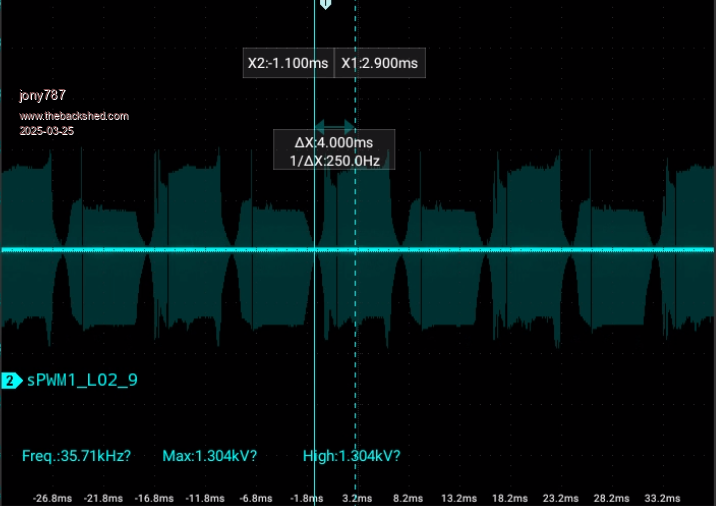 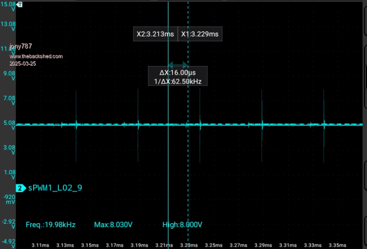 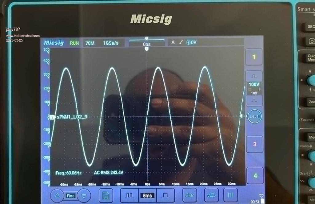 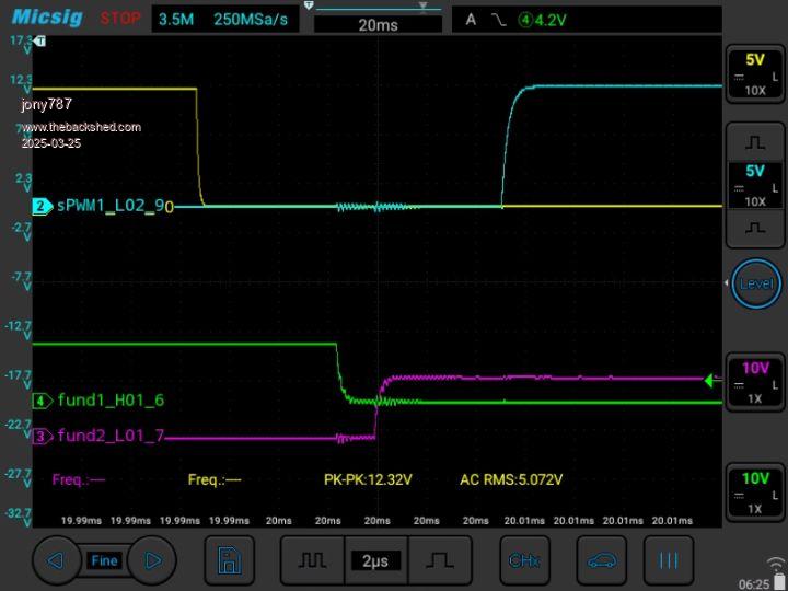 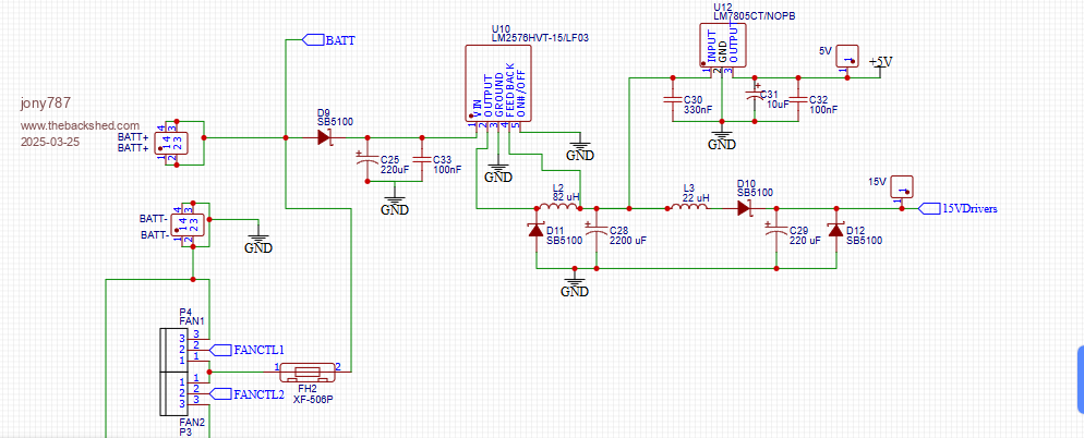 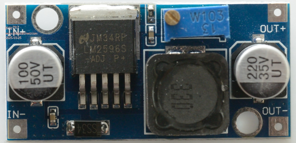 What I’ve Tried: LC filter (82 µH + 2200 µF) after 5V regulator 100nF and 10µF ceramic caps at load Common ground for all circuits Scoped noise is ~20 kHz ripple/spikes riding both VCC and GND Considering isolated DC-DC converter to isolate Arduino and sensors Questions: How are others managing DC-side noise in inverter or high-frequency switching systems? Are you using fully isolated supplies? Any success with ferrite beads, star grounding, or optical isolation for UART? Are you isolating sensor power and ground separately? The sinewave looks good overall with minimal wobble at zero-volt crossover. Thanks to Warpspeed for guidance on transformer tuning—I tuned the secondary close to 90 Hz with a 2.5 µF capacitor. Right now, I'm powering the inverter from a DC bench supply during testing. The sine amplitude scales with DC input. The inverter is functionally working, but I must fix the noise to get reliable AC voltage/current readings. Any feedback, schematics, or scope images showing how you solved similar issues would be hugely appreciated. Thanks in advance. |
||||
| noneyabussiness Guru Joined: 31/07/2017 Location: AustraliaPosts: 527 |
I'll get this started... I had issues with SPI communication and noise on a lcd in my eg8010 setup, lock ups etc. I ended up using shielded Ethernet cable, (Grounded the shielding), it still has locked up once since then in the last 12 odd months.. Just imagine every wire is a antenna, so if possible move it away from sources of " noise " and even try wrapping and grounding the sensor wires.. if you are using a pcb, keep it all away as much as possible and lots of ground plane on noisy lines, shielding and ground where possible.. on a side note, try dropping the 36-50v to say 12v, then drop it to 5v with a linear regulator, quieter and stil low dissipation. I think it works !! |
||||
| jony787 Newbie Joined: 07/01/2025 Location: Puerto RicoPosts: 7 |
Hey noneyabussiness thanks for your reply. I started the project with an Arduino Nano 328p and had a lot of display issues like you mentioned. Using the Arduino Nano Every ATmega4809 have solve almost all my previous display issues. I see your point in terms of the lowering the voltage, I actually go from the battery voltage to 15v via an LM2576HVT-15. before the 5v power stage. I had a LM7805 and the 20khz noise still present. I will look into shielding what I can and will also need to test the inverter connected to the batteries. Ill have to revise the PCB and will look into improving the grounding across the board. Thanks for your feedback. |
||||
| noneyabussiness Guru Joined: 31/07/2017 Location: AustraliaPosts: 527 |
we're you using the onboard regulator on the arduino or external?? why I ask is I've found if your line is noisy the onboard has trouble dealing with it. I usually go silly with filters/grounding when it's bad, ask anyone here how many annoying " problems " have arisen from the slightest unfiltered "noise". especially sensor wires, I try and use cheap shielded Ethernet cable,its a waste sometimes but it works well... I think it works !! |
||||
| KeepIS Guru Joined: 13/10/2014 Location: AustraliaPosts: 2196 |
Nice to see another new forum member in the Inverter area. Just took a break from completely rebuilding my Solar charger system over the past 5 days, whew! There are some posts here about Noise and the Arduino 328P, but obviously it would be applicable to almost any Micro including the EG8010, which I have also used. The Controller board designed by Wiseguy, which is the board I'm using, was designed with a ground plane. In my previous two build I carried out extensive testing with respect to Inverter power stage induced noise, which can sometimes be increased or even overridden by Solar charger noise on the main DC bus feeds - especially at high solar input power. As you noted, the DC bus, both positive and negative carry very high Inverter currents and the resulting magnetic fields can play havoc with a Micro controller board. I had a quick glance at the DSO captures you posted and did not notice anything unusual with respect to Inverter noise. I found an Aluminum ground plate slightly larger then the Controller board, and mounded about 10mm below the PCB made a very noticeable improvement to Inverter noise injection, however it must be connected to the Common Main Bus Negative input on the inverter with a minimum of 2 gauge, preferable 0 Gauge cable, and no more than 200mm in length, no other connection with the exception of the PCB ground plane (if available) via a Cap, is allowed to touch the Aluminum ground plate, including metal work in the inverter. In the latest build the PCB, the combination of small Arduino Nano board mounted on the Controller board, is placed on a ground plate, even though it's a good distance from the Power BUS and Dual Power stages, as noneyabussiness mentioned, cable layout is important to the extent of not running any cables to the Controller parallel to the Main DC BUS unless there is substantial seperation, separate earths back to the main input BUS point is a good idea. I also use isolated power supplies for extra circuitry and driving LEDS and Meters, LCD etc, Wiseguys power board uses fully isolated SUB supplies on the Power board. The result is as follows using the Nano Controller: The serial USB COMS is 100% stable, there is no interference carried across to the USB port of a PC or Laptop that is connected to the Nano Controller, even by 10 meters of USB repeater cable. I assume you are referring to a different screen than the LCD screen I use in my Inverter, this is a separate Nano board driving a 4 LINE LCD, obviously there are zero problems with this approach. The Nano has proven to be 100% reliable in my inverter, running under extreme current and power levels without a single glitch. NANO:Inverter V 8.2ks - Linux AvrDude GUI script V4.1 |
||||
| nickskethisniks Guru Joined: 17/10/2017 Location: BelgiumPosts: 481 |
Can you post some pictures of the whole inverter? Do you have an inductor between h-bridge and transformer? This helps lowering the di/dt and so lowering some emissons. You might want to increase resistance of gate resistors if power layout is not optimal. Each current conducting path to your controller can inject some rubbish, ferrite beads arround i2c for example helps a lot, but you want to find the cause first. Optocouplers for the pwm singals like in wiseguys design, etc.. |
||||
| wiseguy Guru Joined: 21/06/2018 Location: AustraliaPosts: 1297 |
In my early days of noise chasing I quickly determined that sometimes the noise is not having any effect as it may be common to the ground and supply lines and everything in between. This is especially true when very fast rising and falling current levels are being switched as in your inverter, and being monitored with a CRO. Sometimes you can end up spending a lot of time chasing shadows. To determine if this may be what you are experiencing, connect the probe earth clip to the probe tip and touch the (now grounded) tip to the chassis or the ground wire of the inverter whilst it is running. (The supply rail can be monitored too but use a 10 nano ceramic in series with the grounded probe tip). You may need to experiment with the trigger level to see the "noise" in question. Whilst intuitively the noise may appear to be the issue do treat everything else as suspect too - until proven innocent. I agree with KeepIS the waveforms looked typical to me, I was going to ask how you got it so quiet  Edited 2025-03-27 20:56 by wiseguy If at first you dont succeed, I suggest you avoid sky diving.... Cheers Mike |
||||
| tinyt Guru Joined: 12/11/2017 Location: United StatesPosts: 561 |
I don't know if this will help. Since you are revising your PCB, together with the ground plane under the Arduino Nano Every, enclose the top of the module in metal can connected to the ground plane. Also put an R/C or L/C filter outside the metal can but close to it at every pin of the module. Edit: Except for the GND pins of the module, these should be connected directly to the ground plane. This way even if it is noisy outside the metal can, hopefully the module is shielded from it. 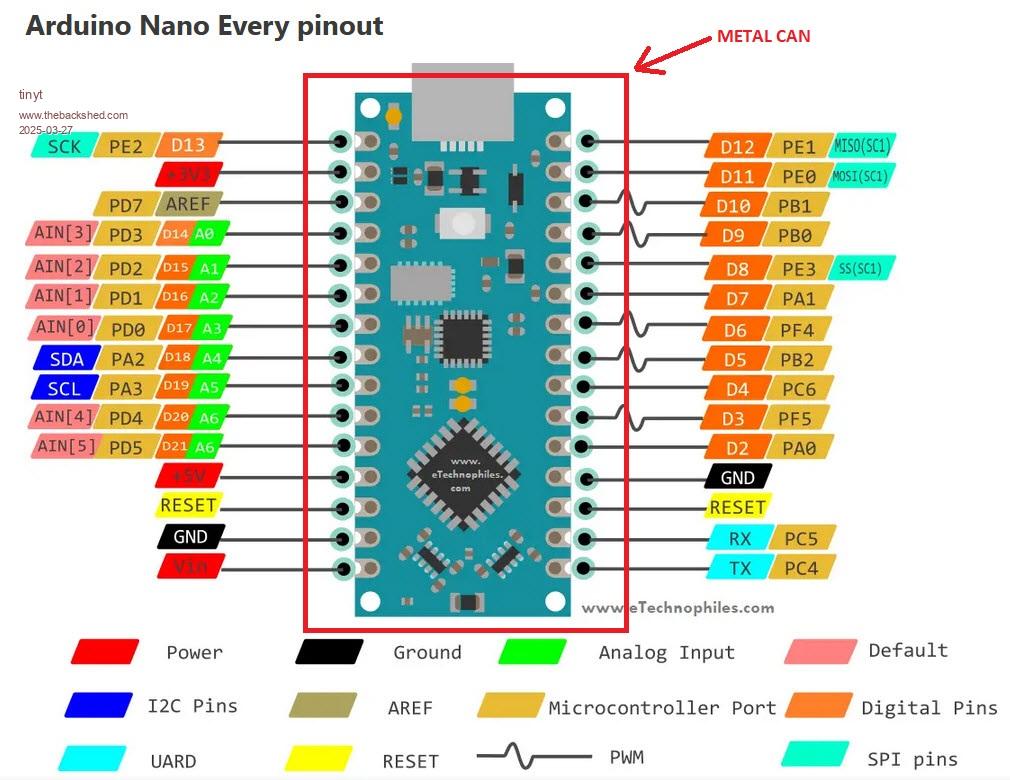 Edited 2025-03-28 00:33 by tinyt |
||||
| The Back Shed's forum code is written, and hosted, in Australia. | © JAQ Software 2026 |
