
|
|
Forum Index : Electronics : Questions regarding Diode drop on solar charger.
| Author | Message | ||||
| CaptainBoing Guru Joined: 07/09/2016 Location: United KingdomPosts: 2171 |
Afternoon forum, hope you are all well. I have built a data logger that has a small battery of 4xAA NiMh cells (so nominally 4.8V but actually seems to sit around 5.2V here) From the scrap box, I found a solar panel about A6 size that gives 6.1V in bright sun with a short circuit current of about 120mA The panel currently charges the battery through a single schottkey blocking diode and it all seems quite happy - it does what I expect. I have some quite severe energy saving designs in the hardware for the sensors and radio transmitter (MOSFET hi-side switches) and a *lot* of CPU SLEEPs in the code. I cache the data overnight and only transmit during daylight. Battery voltage drops to about 5.2V overnight but as the sun comes up, in today's blustery weather with bright bits, VBAT comes up as usual to about 5.4V with VSOL occasionally hitting 5.8V. I sense both solar and battery voltages through potential dividers with D1 and D3 clamping anything nasty to the supply rails and then onto AIN pins, applying a multiplier in the prog to give "real" voltages. All works nicely, but we are coming up to maximum daylight and I am wondering about six months from now when we might be lucky to get 8 hours of heavy overcast. 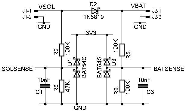 I am conscious of the voltage drop across D2 and sure enough the trend shows the expected 0.3v-ish difference between VSOL and VBAT (of course VSOL will be dragged down towards VBAT as it tends to short circuit). Clearly this is very blunt and I don't have space or $$$ for some MPPT controller (hence NiMh cells which are quite forgiving). 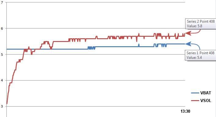 So now I start thinking about an "ideal diode" circuit (4 components) in an effort to eliminate the "lost" 0.3V and bench tests suggest I might get it down to about 50mV, but does pose some questions for me as I have never done this stuff before. Ideal Diode schematic and discussion 1. I expect to get a lot more usable energy into the battery - do you see any problems? 2. How do I measure the energy going into the battery? With no voltage drop, I expect ~voltage parity on both sides 3. Should I put a resistor in series? I am thinking 10Ω just to be a bit nicer to the panel and allow the voltages to seperate a bit. 4. what else am I missing? all input gratefully recieved - thanks in advance h Edited 2025-05-29 23:30 by CaptainBoing |
||||
| phil99 Guru Joined: 11/02/2018 Location: AustraliaPosts: 3317 |
Depending on the mA-Hour capacity of the cells you may not need to add any series resistance. A continuous charge current up to 1/20 of the mA-Hour capacity is usually ok. Your solar panel effectively has a series resistance of 50Ω anyway. A simpler option than the ideal diode circuit may be just a bigger diode. Schottkey diodes don't have the sharp fixed voltage turn-on that rectifier diodes have so a 10A schottkey might drop about 100mV at such a low current. |
||||
| CaptainBoing Guru Joined: 07/09/2016 Location: United KingdomPosts: 2171 |
hey Phil - thanks for that. the battery is 4x 2450mAh Ikea "Ladda" so actually quite nice cells (I think you can also get them in 1900mAh too) - 5% of that is just about the measured s/c current of the panel so I might just get away with no ballast resistor. That is a really nice idea re a beefier diode - it had not occurred to me to go that way at all. I don't have any such devices but they are only a search away. I have some tiny boards coming to build the ideal diode on so I can try both solutions really easily. The unit is on soak test just now. It is approaching a week "in the wild" and not a hiccup so far... lots of improvements in the software have come out of it and it is already generating interesting data. It seems to charge itself and run nicely, which was a big worry - never seen the battery dip below 5.2V yet and 5.4V (which is the highest I see) is 1.35V per cell so just about optimum anyway... which is nice for early summer but I expect when we hit the dreary days of autumn and winter that panel really will need to squeeze every joule it can out of a weak, low sun. As an aside, I used LoRa for the comms and had to play about with sensitivity and antenna design a bit, but so far it has sent over 280KB with only a single dropped packet (99.986% reliability) - well impressed as the radio path is a bit fraught and reciever is on the back side of a building away from the box. It is currently sending 76 characters in two packets every 72 seconds, which is much faster than necessary or intended (I was going to do once an hour) but I had it that fast so I got regular updates on the battery and granularity enough to see the panel performance as the light levels change (that alone suggested some useful tweaks for the software). Seeing that the electrical system can sustain that, I have decided to go for 10 times an hour which will be kinder on the power reqs but still reasonably fine-grained. thanks very much for your input! h Edited 2025-05-30 01:18 by CaptainBoing |
||||
| CaptainBoing Guru Joined: 07/09/2016 Location: United KingdomPosts: 2171 |
BLIMEY! so I have been prattling on about the Vf of my chosen Schottky barrier diode in my solar charging circuit (see above) I tried @phil99's idea of a bigger diode (thanks for that) so as to take advantage of it's gentler conduction curve and it was better but with both 10A and 20A variants, Vf was still around 300mV you can see my dilemma here - was a fairly bright start to the day but now is very gloomy with rain on the way (trace ends at about 2PM, so very dull afternoon). 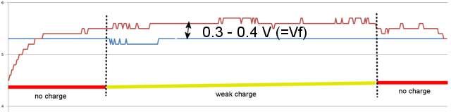 everything with those red lines and VSol>VBat could be putting a weak charge in to the battery. So I got some cute little boards made up for the four component Ideal Diode and assembled/tested one this lunchtime. Tests I had already done with what I had, suggested I might get Vf down to about 50mV which was very desireable... but, errrr...  Vf=10mV!  with the diode into a 56Ω load at 6V (i.e. to draw ~100mA) which are the maximum characteristics of the little solar panel I am using (which I won't get in reality). with the diode into a 56Ω load at 6V (i.e. to draw ~100mA) which are the maximum characteristics of the little solar panel I am using (which I won't get in reality).So, the question is: "how much 'ideal' is too much?" and what issues do you guys see if I put this in parallel with D2 (easier than replacing)? cheers h Edited 2025-06-12 23:23 by CaptainBoing |
||||
| Godoh Guru Joined: 26/09/2020 Location: AustraliaPosts: 675 |
You could always take the diode out of circuit all together and see what the results are. I have done it many times over the years when using solar panels in parallel. I just let the regulator do its work and deleted all the blocking diodes. it may be a good experiment to see if any current actually goes back through the panel at night anyway. Or you could make a small circuit with a LDR and a transistor to block current flow in reverse in low light conditions if there is actually any reverse current pete |
||||
| CaptainBoing Guru Joined: 07/09/2016 Location: United KingdomPosts: 2171 |
morning Pete. You well? I agree that solar panels are "just" photo-diodes and so nothing flows into them, but it just doesn't sit right with me not to have some blocking which I can control - it probably says more about my trust issues over mass-produced, anonymous chinese stuff than anything. If the panels were 50V+ jobbies, the 0.3V of the barrier is immaterial, but I am using a 6V one (bright sun) so Vf of D2 represents a considerable loss of potential. I like your idea of connecting through a light-controlled switch, and it certainly scratches my itch about the "wasted" power. Another idea from the forum that has got legs! Thinking about it, I already monitor both voltages so I could probably do this in software - skip the LDR and just have a FET that gets switched in. hmmmmm. This is pretty much what the ideal diode does except the voltages are subject to a hardware comparator formed of the matched pair of PNP transistors. I could replace that side of things with a few lines of code. I have the ideal diode built and ready to go and at 10mV it is almost the short-circuit that I seek. 10mV out of the panel's 6V (although unlikely) is 0.16% loss - way better than the 5% (probably much worse) I am getting now. I have been watching the traces this morning and it grinds my gears to see dV (VSol-VBat) at just +0.2v and know that nothing is going into the battery, whereas with a "short", the battery would be sucking every last joule from the panel - I aspire to that. I'm gonna fit the Ideal diode this weekend (or maybe today). I anticipate the voltage traces will become a single line when dV>0 as it will be around a tenth of the resolution of reporting... will tweak that in the next software. cheers h Edited 2025-06-13 19:55 by CaptainBoing |
||||
| CaptainBoing Guru Joined: 07/09/2016 Location: United KingdomPosts: 2171 |
Last words on this - probably. I went ahead and got the logger into the shed and fitted the Ideal Diode circuit board across D2. Below is the trace for the day (almost). The circuit runs as expected and the traces look very healthy. 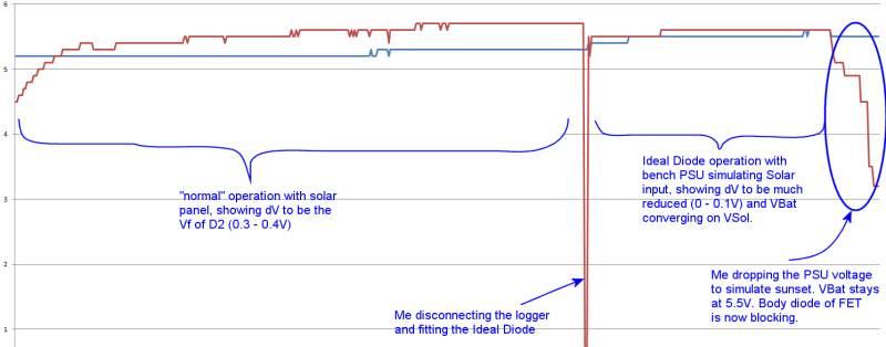 Next step is to load the new software and put it back in the wild... which will be tomorrow so I can continue to monitor batter use over night. cheers everyone that gave suggestions. h |
||||
| Godoh Guru Joined: 26/09/2020 Location: AustraliaPosts: 675 |
Hi Captain yes I am well thanks. I am getting older like all of us, but doing fine. I hope you are well too.It looks like you have the ideal diode setup going well. Have fun Pete |
||||
| The Back Shed's forum code is written, and hosted, in Australia. | © JAQ Software 2026 |
