
|
|
Forum Index : Electronics : Gerry's Wiseguy Inverter Build
| Author | Message | ||||
disco4now Guru Joined: 18/12/2014 Location: AustraliaPosts: 1109 |
I am to the exciting bit of my Wiseguy inverter testing. Tests 14/15 where the control board and the power board are still on current limited supplies, two 560uF caps are in place, the choke and toroid are connected and a 1uF capacitor is across the a/c side. At about 12-13V applied to the power board the a/c output starts and the output wave is shown below. Increasing supply voltage >13v causes current draw to increase above 500mA (tried up the 1A so not just on the margin). The wave form looks like its missing one quarter (would look OK if it was not missing). Any suggestions where to look. Checking the Power board for something around the wrong way? Inverter a/c Output 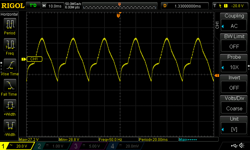 F4 H7FotSF4xGT |
||||
| KeepIS Guru Joined: 13/10/2014 Location: AustraliaPosts: 2115 |
 Current at 14V should be around 300ma. I don't have wiseguys info on the PC I'm on at the moment. So assume you are measuring AC output? I ask because it would be more like half the waveform missing if start vert ref is mid screen. What was the controller outputs like, I think WG had them in his tests, but I'm not sure? NANO:Inverter V 8.2ks - Linux AvrDude GUI script V4.1 |
||||
| disco4now Guru Joined: 18/12/2014 Location: AustraliaPosts: 1109 |
Yes measuring AC output. The vertical 0 is where the 1> pointer is on the screen grab above. AC or DC couple shows the same thing. There is no earth connection on the AC output except when the DSO probe is connected. I have not looked at the input waveforms, will have to research what they should look like. What will happen it I pull the Opto's out one at a time to narrow it down. Will the FETs just not turn ON or will they always be ON. F4 H7FotSF4xGT |
||||
| KeepIS Guru Joined: 13/10/2014 Location: AustraliaPosts: 2115 |
That is not the best way, the current is low at 13v, and you have small caps, you could look at the opto in and out wave forms. So full waveform but with distortion. Have you checked that 1uf 300vac rated cap across the output, usually 3uf is a better value, just making sure it's not something simple like a dodgy cap. You can take the Toroid off and use a small RC network across the board output, but need to look up the values, been a long time since I touched mine. NANO:Inverter V 8.2ks - Linux AvrDude GUI script V4.1 |
||||
| phil99 Guru Joined: 11/02/2018 Location: AustraliaPosts: 3166 |
The output of the transformer can never have a DC offset so it will always be fairly symmetrical and AC or DC coupling will make no difference. The primary side will give a better indication. If you don't have a differential probe 2 standard ones will do (assuming the scope is 2 channel) with one trace inverted to make comparison easier. If it has math functions subtract ch2 from ch1. If single channel save the waveforms for each side and compare them on the computer. What looks like a negative quarter cycle could be an inductive spike from the transformer, rounded off by the output capacitor, if one or two MOSFETs aren't switching on. That would also explain the higher current as there would be a DC component to the waveform. The DC resistance of the primary is almost zero. At full voltage perfect symmetry is essential to avoid saturation. Edited 2026-02-28 17:45 by phil99 |
||||
| KeepIS Guru Joined: 13/10/2014 Location: AustraliaPosts: 2115 |
FYI: I was alluring to swapping the toroid for a RC load to not only remove the toroid from the equation, but at the same time, allowing measurements on the power board without having a nail as a load for the FETS if a slip happens. Not interested with DC offset. NANO:Inverter V 8.2ks - Linux AvrDude GUI script V4.1 |
||||
| wiseguy Guru Joined: 21/06/2018 Location: AustraliaPosts: 1267 |
Hi Gerry - on holidays again so away from pc. I would be looking at the opto couplers/drivers. One reversed maybe or cheap sockets gave me that result (optos were oriented ok). Look at the gate drives - no supply needed on FET main supply only the 12v from controller. If at first you dont succeed, I suggest you avoid sky diving.... Cheers Mike |
||||
| wiseguy Guru Joined: 21/06/2018 Location: AustraliaPosts: 1267 |
Check orientation of the smd drive transistors. There was also an issue on some early PCBs that needed a short on one trace to ground be removed. Not sure if I can access the info here but it was in the thread when boards were being ordered. If at first you dont succeed, I suggest you avoid sky diving.... Cheers Mike |
||||
| disco4now Guru Joined: 18/12/2014 Location: AustraliaPosts: 1109 |
Thanks for the ideas. The short to GND on R6 I am aware of and was fixed during construction. Just trying to get to grips using the DSO and what I should be seeing at various points. F4 H7FotSF4xGT |
||||
| KeepIS Guru Joined: 13/10/2014 Location: AustraliaPosts: 2115 |
Gerry if needed, I have some close up pix of the power board on my thread, but I have more if you want to post a pix of the board, I can compare it, otherwise I'll look for pix of that version board and post if needed, I made a few. Mike whats a holiday? I don't remember them  If all of that reads funny, I'm in a rush  NANO:Inverter V 8.2ks - Linux AvrDude GUI script V4.1 |
||||
| wiseguy Guru Joined: 21/06/2018 Location: AustraliaPosts: 1267 |
What is a holiday ? = Stop having fun in the shed and take me on a trip somewhere where there are no soldering irons, CRO's or meters to distract you! The holidays will continue until morale improves   If at first you dont succeed, I suggest you avoid sky diving.... Cheers Mike |
||||
| disco4now Guru Joined: 18/12/2014 Location: AustraliaPosts: 1109 |
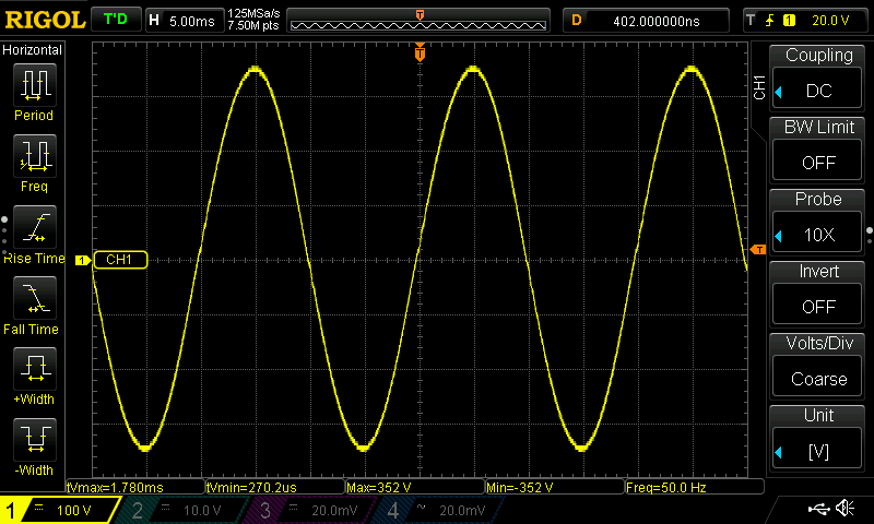 Well that looks better. Thanks for the pointers everyone. It was good to track it down having a look at the signals with the DSO. I learnt a lot more than if I had just visually noticed the bent pin on that FOD3182 Gate Drive Optocoupler. I used two channels on the DSO with MATH A-B to do the probing of the signal. I could not see anything like the expected pulse type waves anywhere. I had the LCD connected and could see the PWM% on that display was 0.1% With Mike's (@KeepIS) later software the PWM won't start until VCAP is close to VBAT. I disconnected the VCAP sense wire between the Power Board and the Controller and connected it to the power on the Controller board. Mike's note below applies also if power board is connected but not powered. PWM% was now 100% and the waveforms looked a bit like I expected. I probed the outputs of the Optocouplers (pins 6&7) and one did not appear to be giving an output. I pulled it out to change it and noticed a bent pin that was not getting into the socket. I adjusted the pin a put it back and it had output. I then powered up the Power Board and all was well, 250mA current when 48V applied. So the original post shows the output with one Opto not driving, which also results in greater than expected current draw due to the imbalance. The note from Mike's Latest Changes.txt If you want "Test mode" without Power Boards, make a plug for the Controllers SPWM output connector and connect the Vcap pin (both Vcap pins in Dual Mode code) via a 1K resistor to the controller DC input line. Gerry F4 H7FotSF4xGT |
||||
| wiseguy Guru Joined: 21/06/2018 Location: AustraliaPosts: 1267 |
Congrats! Seeing that first clean sinewave it’s just like love at first sight hey lol If at first you dont succeed, I suggest you avoid sky diving.... Cheers Mike |
||||
| KeepIS Guru Joined: 13/10/2014 Location: AustraliaPosts: 2115 |
NANO:Inverter V 8.2ks - Linux AvrDude GUI script V4.1 |
||||
| disco4now Guru Joined: 18/12/2014 Location: AustraliaPosts: 1109 |
Setting up STARTUP I decided to use the second startup circuit when I setup the Run/Stop functionality. I think there maybe a problem with it. Switching from STOP to RUN starts it up nicely, switching back to STOP stops the PWM and then releases the solenoid, however the solenoid is then repeatedly re-energised and released until the main supply is disconnected, when it slowly dies away with the solenoid chattering away while the voltage fades. I placed a diode bypassing the diode and resistor feeding the caps to give a path for the caps to feed 48v once the solenoid is open (i.e. made it like first circuit) and it works as expected. What I think is happening in circuit 2. When the solenoid opens it removes the 48V from BOTH the STOP path and and the 48V to the controller. This means the STOP path that switches FET Q10 on, which then bypasses the bottom resistor of the potential divider used to monitor VBat so that VBat reads low is no longer effective. This would happen almost immediately I think. However, removing 48v from the controller does not immediately kill the 12v and 5v supplies, so the controller probably has time to think all is OK and switch the solenoid on again. The controller get a quick recharge, STOP has 48v again and shunts the potential divider, controller opens the solenoid and it all starts again. I am happy to use circuit 1, but interested to know if my theory seems plausible. The StartUp circuit from here 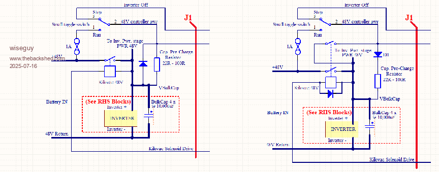 Edited 2026-03-05 11:56 by disco4now F4 H7FotSF4xGT |
||||
Revlac Guru Joined: 31/12/2016 Location: AustraliaPosts: 1240 |
Been a while since I did this but remember something similar happening, on circuit 2, I think I just put a jumper across the diode and intended to tidy it up later. One of the other Schematics (think its the 2 stage inverter) has the diode omitted. Footnote added 2026-03-08 21:25 by Revlac Just found the Auto start version I used....WG39 Rev6 Auto Start version, Nano Rev 6 Also, WG39 Auto Start & Stage 1&2... is similar I have just jumped (bypassed) the diode, it works perfectly well when the Controller board is in Run Mode, when turned off it will slowly drain power from the CAP Bank until the screen goes out, very happy with it this way. When in test Mode, switch controller off and the main isolator has to be turned off to completely power down the inverter.  Cheers Aaron Off The Grid |
||||
| FET cemetery Regular Member Joined: 17/04/2024 Location: AustraliaPosts: 73 |
I had the same problem, chattering solenoid with circuit 2, no problems with circuit 1. Had me scratching my head for a while. No stone unturned, no FET unburned. |
||||
| mab1 Senior Member Joined: 10/02/2015 Location: United KingdomPosts: 277 |
I had the same issue, but it (the 2nd circuit) turned out to be an earlier version of the startup circuit iirc. The 1st circuit is the one to use |
||||
| KeepIS Guru Joined: 13/10/2014 Location: AustraliaPosts: 2115 |
Wiseguy and I had a discussion about this somewhere, might have been via email in the very early days of his development and my brutal demonic testing of the WG designs, almost to the limits, and past them sometimes. The circuit on the left (1) is almost how I did mine from the start, although I do not have a diode across the Pre-Charge R. It has never misbehaved. BTW, back when you were talking about removing the optos and checking them, for some insane reason, I was under the impression that they were soldered in, so I though measure first  Once again, great to see it running NANO:Inverter V 8.2ks - Linux AvrDude GUI script V4.1 |
||||
| wiseguy Guru Joined: 21/06/2018 Location: AustraliaPosts: 1267 |
Still on holidays but I think I can see what is going on in circuit 2. Gerry is on the right track. You may notice that the Kilovac solenoid shows a diode across the coil. I forgot to mention that this diode should be fitted externally from the Nano board and D18 removed on the Nano controller PCB. It appears the 48V capacitor bank has a sneak path back through the Kilovac solenoid coil through D18 to the 48V supply on the Nano Controller. Switching the inverter to OFF does open the second contact from the Kilovac and removes direct 48V from the controller, but the sneak path through the Kilovac coil and D18 restores ~Vcap to the controller and as 48V and Vcap bank are the same so it closes the solenoid again restoring the stop signal etc. I have not tried it but I am pretty confident circuit 2 should work ok with D18 removed from the Nano PCB and the Kilovac solenoid diode mounted across the solenoid coil. In retrospect if D1 (precharge diode) is simply shorted out in the second circuit it would probably work ok without removing D18, as 48V (and the stop signal) is maintained to the Nano PCB via the precharge resistor which should hold the stop signal "off" until Vcap bank has fallen to Less than Vlow input level. I will confirm when I get back to my work bench unless someone tries it first. If at first you dont succeed, I suggest you avoid sky diving.... Cheers Mike |
||||
| The Back Shed's forum code is written, and hosted, in Australia. | © JAQ Software 2026 |
