| |
  Page 2 of 2 Page 2 of 2 |
| Author |
Message |
poida

Guru

Joined: 02/02/2017
Location: AustraliaPosts: 1497 |
| Posted: 07:28am 30 Jun 2026 |
 Copy link to clipboard Copy link to clipboard |
 Print this post |
|
good going Bryan
If you find even a little choke that uses a ferrite core, you might be lucky and
get the sort of result I got (a straight line then increasing steepness).
Don't worry if your results look different to mine.
Ferrite cores are way different to the very thin laminated Iron core that you are testing now.
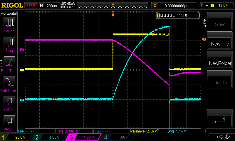
I just tested a large Aerosharp choke with 6 turns.
the current curve looks just like yours.
The Purple trace is voltage and it drops 3 volts, down from the 12V start point
during the pulse.
wronger than a phone book full of wrong phone numbers |
| |
Bryan1

Guru
Joined: 22/02/2006
Location: AustraliaPosts: 2297 |
| Posted: 01:15am 01 Jul 2026 |
Copy link to clipboard |
Print this post |
|
Well decided against taking the choke out of my inverter as down the track I will be building another Madboard and they can be tested then.
Awhile I played with one of those Temu induction heaters where I did manage to let the magic smoke out with my copper coil mod's 
Anyway decided back then to build my own which became one of those projects to finish and went into somewhere in the shed
Found the toroid I made for the project so decided to give it a test.
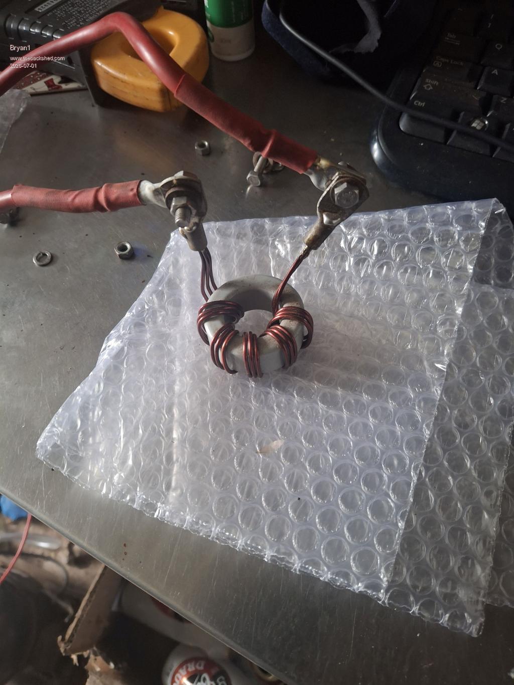
This is the 210us pulse which works out to 10.5uf and 240A
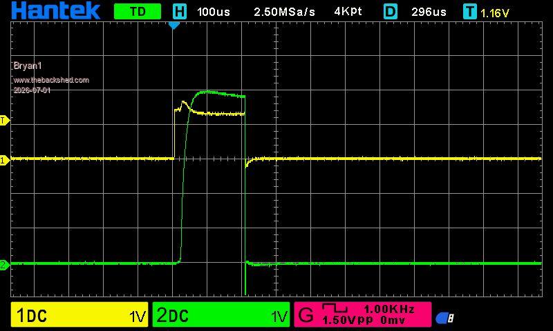
The 310us pulse which works out to 12.45uf and 300A
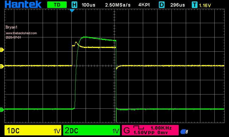
The 400us pulse which drops to 2.4uf and 205A
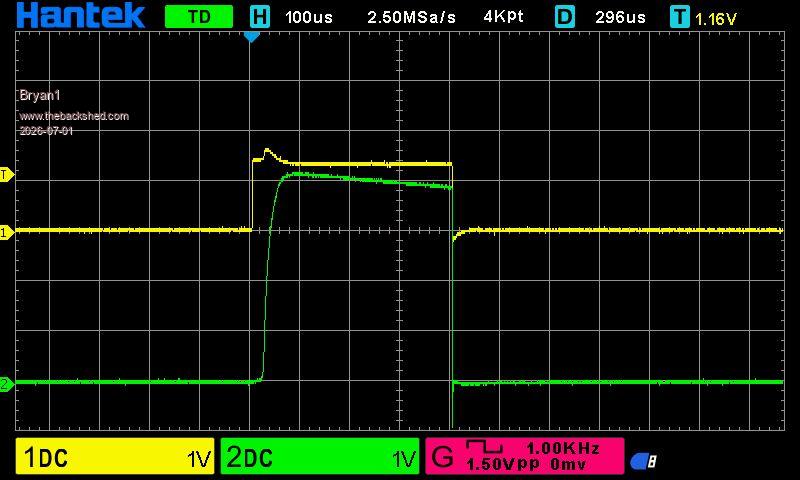
So may be time to get the second one made and revisit this project.
Regards Bryan |
| |
phil99

Guru
Joined: 11/02/2018
Location: AustraliaPosts: 3412 |
| Posted: 01:54am 01 Jul 2026 |
Copy link to clipboard |
Print this post |
|
It looks like your capacitor bank is running out of charge after 50µS with such a low inductance.
To get a better look at what that inductor is doing perhaps reduce the pulse width to 50µS and set the scope time base to 10 or 20µS/Div.
Edited 2026-07-01 12:01 by phil99 |
| |
Bryan1
Guru
Joined: 22/02/2006
Location: AustraliaPosts: 2297 |
| Posted: 02:43am 01 Jul 2026 |
Copy link to clipboard |
Print this post |
|
Rather than use this thread for my testing it may be better to start a new thread for this Induction Tester. |
| |
GleamBright
Regular Member

Joined: 21/04/2025
Location: AustraliaPosts: 44 |
| Posted: 11:57pm 07 Jul 2026 |
Copy link to clipboard |
Print this post |
|
I have in my build notes a comment by Poida that if the input voltage is going to be more than 85V, R6 should be changed from 2K7 to 1K5 or 1K. Does this mean that if I do so, I should no longer operate at 85V? ie., should R6 be no greater than 1K5? |
| |
KeepIS

Guru
Joined: 13/10/2014
Location: AustraliaPosts: 2282 |
| Posted: 12:45am 08 Jul 2026 |
Copy link to clipboard |
Print this post |
|
R6 appears to part of a voltage divider for measuring the Solar array voltage.
If your solar voltage is above 85V, change the value to 1k5, or you may need 1k if the voltage even higher.
If the resistor value is incorrect, you won't be able to adjust/calibrate the Solar voltage setting in the menu for the correct solar input voltage.
Ideally you want to be able to see the VOC "open circuit voltage" on the LCD.
Look up the VOC data for the panel, add them together for each series panel, two panels in series will likely be between 72v and 98v VOC.
If unsure, fit a 1k and see if you can calibrate the menu setting to display the correct voltage.
I'm sure someone who has one of these running will help with the values they used for their solar panel voltage.
.
Edited 2026-07-08 14:01 by KeepIS
NANO:Inverter V 8.4ks - Linux AvrDude GUI script V4.1 |
| |
kentfielddude
Senior Member

Joined: 09/05/2019
Location: United StatesPosts: 121 |
| Posted: 12:55am 11 Aug 2026 |
Copy link to clipboard |
Print this post |
|
Where can I find the latest gerber files and schematic for the mppt? |
| |
wiseguy

Guru
Joined: 21/06/2018
Location: AustraliaPosts: 1326 |
| Posted: 01:36am 18 Aug 2026 |
Copy link to clipboard |
Print this post |
|
Sorry for the late response please send me a pm with your contact details if you are still looking.
If at first you dont succeed, I suggest you avoid sky diving....
Cheers Mike |
| |
poida
Guru
Joined: 02/02/2017
Location: AustraliaPosts: 1497 |
| Posted: 07:40am 18 Aug 2026 |
Copy link to clipboard |
Print this post |
|
thanks for handling this, Mike.
wronger than a phone book full of wrong phone numbers |
| |
wiseguy
Guru
Joined: 21/06/2018
Location: AustraliaPosts: 1326 |
| Posted: 01:48pm 18 Aug 2026 |
Copy link to clipboard |
Print this post |
|
Hi Pete, all part of the service lol albeit a bit slow though....
If at first you dont succeed, I suggest you avoid sky diving....
Cheers Mike |
| |
| |
Page 2 of 2 |

 Notice. New forum software under development. It's going to miss a few functions and look a bit ugly for a while, but I'm working on it full time now as the old forum was too unstable. Couple days, all good. If you notice any issues, please contact me.