
|
|
Forum Index : Electronics : Induction Tester
| Author | Message | ||||
Bryan1 Guru Joined: 22/02/2006 Location: AustraliaPosts: 2112 |
G'Day Guy's, Well this thread is for my trials testing out Poida's Induction Tester where I designed a PCB and got it working off the first draft  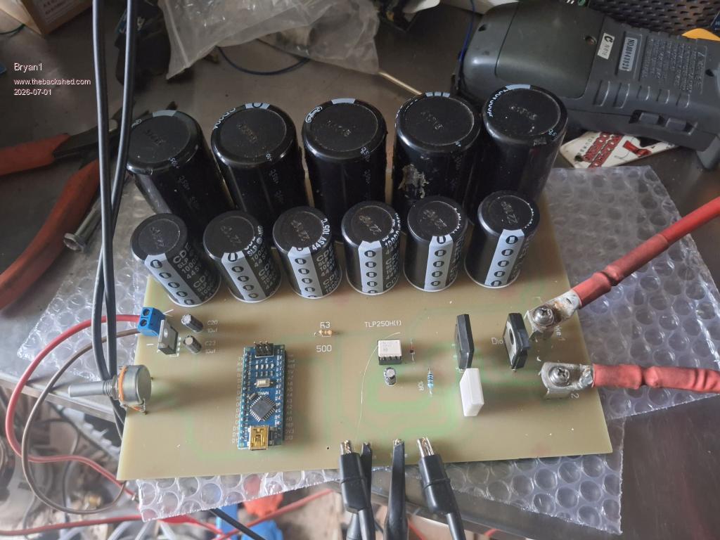 Now the board has 62,800uf worth of capacitors using 6 off 25 volt 10,000uf and 5 off of the 560uf capacitors off the aerosharp board. Now as I am still learning PCB design with Sprint Layout larger holes were needed as I only did 1.5mm holes. A 1.7mm drill was used to open up the holes so the larger components would go in. The 5K pot I used was a smaller size so to get it too fit I just soldered on some legs off a TO-247 old chip to each pot contact. Now the dual diode is also a TO-247 and I only put a 220 chip spacing so just bending the outer legs got it fitting nicely. I made a couple of inductors using a single 42mm diameter grey toroid with a 24mm hole and 17mm thick. I put 3 inhand 1.6mm wire with 5 turns, now my in DMM induction tester show .320mf the induction tester does show the true uf value with is very low. 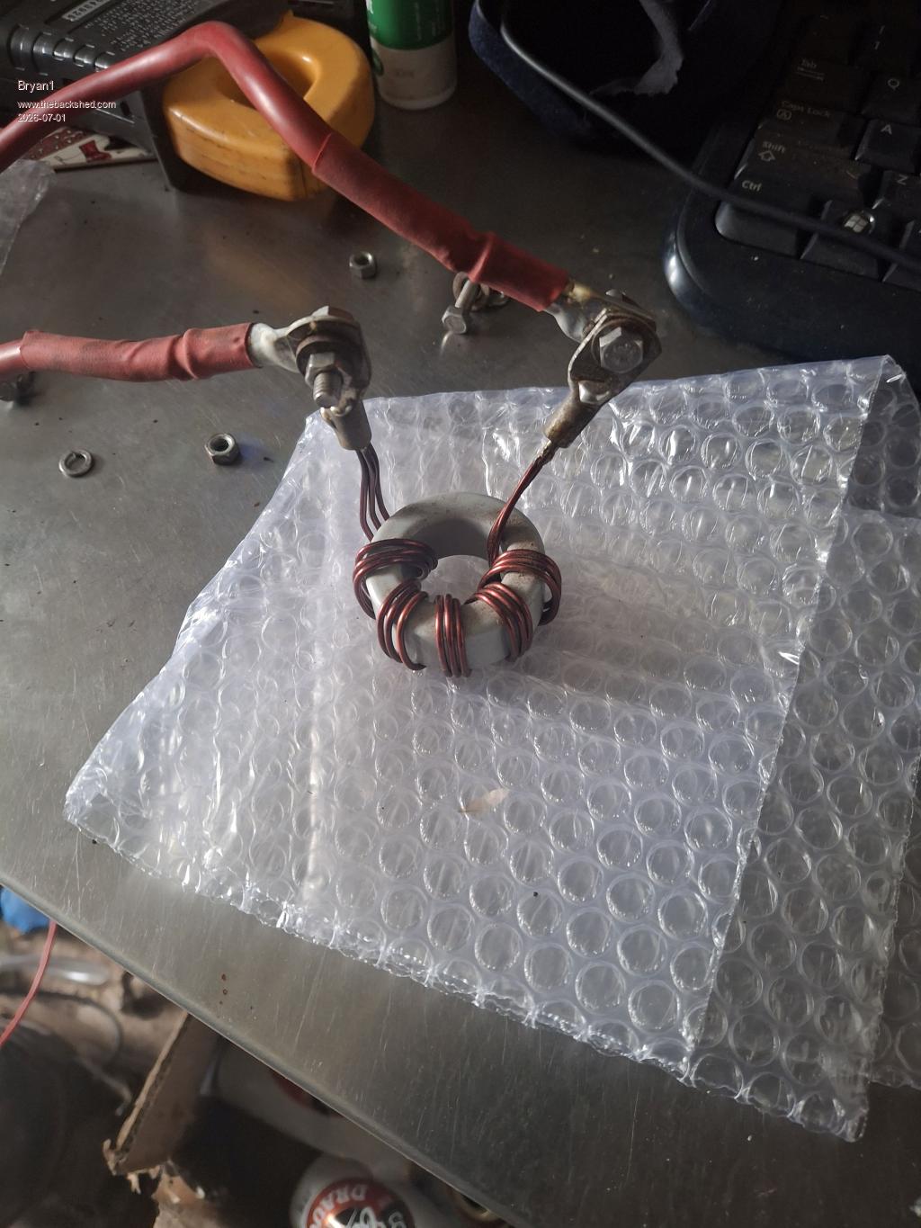 Now I have been using the 100us timebase so with Phill's suggestion I shortened the timebase to 50us and went with shorter pulses. 50us 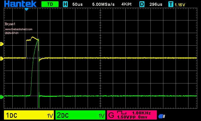 100us 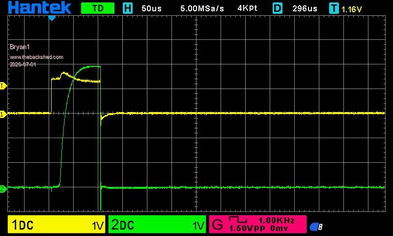 150us 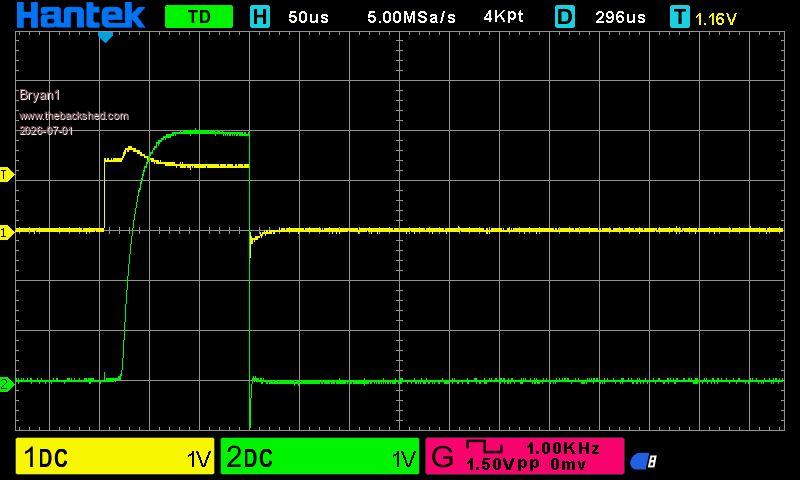 250us 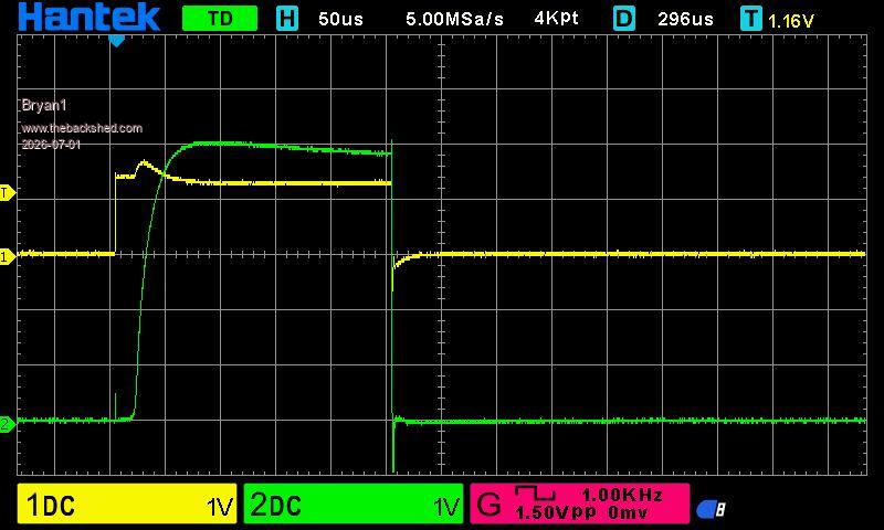 Now after 350us the sense pulse breaks down. So overall I am happy this induction tester is working and I do have 4 spare boards if members want any. Regards Bryan |
||||
| KeepIS Guru Joined: 13/10/2014 Location: AustraliaPosts: 2179 |
If that small toroid is high frequency material, the inductance would be tiny and it would likely saturate with just a few Amperes, it just looks like a complete saturation curve, or something is not quite right in the high current paths between the caps FET and choke? Of course, I could be totally wrong  NANO:Inverter V 8.2ks - Linux AvrDude GUI script V4.1 |
||||
| nickskethisniks Guru Joined: 17/10/2017 Location: BelgiumPosts: 478 |
It would be nice to see the cap voltage instead of the yellow, gate pulse? Like someone else allready said the cap voltage is probably sagging or close to zero, normally the current (green) should skyrock thrue the roof instead of being constant or bending to the right. Allthough the tester is doing what it's supose to do it lacks capacitance to sustain high current with limited voltage sag, you need to zoom in a lot to make sense of the curve, like 1-5us? Soon as your cap voltage sags to much the inductance you want to calculate based on di/dt is not true anymore, you need a constant (or close) voltage in the caps to have an accurate measurement. Best way to maximize the potential of the caps is to use as high voltage as they can handle and use smaller pulsewidth. 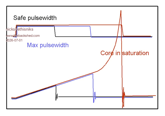 Edited 2026-07-01 17:21 by nickskethisniks |
||||
| poida Guru Joined: 02/02/2017 Location: AustraliaPosts: 1478 |
Nicks, that is an excellent illustration. wronger than a phone book full of wrong phone numbers |
||||
| KeepIS Guru Joined: 13/10/2014 Location: AustraliaPosts: 2179 |
This, but you will need to modify the circuit slightly for the opto supply rail. NANO:Inverter V 8.2ks - Linux AvrDude GUI script V4.1 |
||||
| The Back Shed's forum code is written, and hosted, in Australia. | © JAQ Software 2026 |
