Notice. New forum software under development. It's going to miss a few functions and look a bit ugly for a while, but I'm working on it full time now as the old forum was too unstable. Couple days, all good. If you notice any issues, please contact me.
analog8484 Senior Member Joined: 11/11/2021 Location: United StatesPosts: 254
Posted: 05:49pm 15 Nov 2026
Copy link to clipboard
Print this post
Interesting. I didn't know the LEM sensors can be permanently affected like that.
Totally agree it's not time yet to focus on such things. Just curious if it's something to keep in mind as potential cause of odd behavior.
I had thought about such self calibration that the inverter could do periodically or during startup. I think it would probably require more switches/relays (e.g. disconnect the output, connect the sensor inputs to ground, etc.).
analog8484 Senior Member Joined: 11/11/2021 Location: United StatesPosts: 254
Posted: 06:14pm 15 Nov 2026
Copy link to clipboard
Print this post
Congrats on a great milestone. Great to see it working with the dreaded hair drier load. The waveform is much nicer than what Keepis posted for his hair drier IIRC. Perhaps Keepis could test soon.
I believe the control enhancement for unbalanced loads is now better than what's available in many commercial LF inverters including Victron and Schneider. Assuming the required add-on HW components are cheap enough at scale, I would not be surprised if it shows up in Chinese LF inverters in the near future Edited 2026-11-16 04:16 by analog8484
phil99 Guru Joined: 11/02/2018 Location: AustraliaPosts: 3454
Posted: 10:42pm 15 Nov 2026
Copy link to clipboard
Print this post
Re the current sensor zero offset. A partial solution may be at power-up, before driving the MOSFETs, measure and save the current sensor output. This wont fix drift that occurs while running, so not much help for an inverter that is running all the time as the high peak current of motor starts will likely cause a change in offset, but for a standby inverter may be of some value.
An a place to start experimenting for a fix while running might be to compare the positive and negative peaks. When they are "almost" the same assume they are actually exactly the same and set the zero current point halfway between. Defining "almost" may be tricky.
A possible explanation may be turbulence in the airflow combined with a significant temperature coefficient of the resistance wire in the element. Fluctuations in the airflow will vary the rate of cooling of the wire causing the resistance to vary. Nickel and chromium are getting expensive so perhaps cheaper alloys are being used in consumer products. For it's intended purpose such fluctuations don't matter.
poida Guru Joined: 02/02/2017 Location: AustraliaPosts: 1516
Posted: 06:14am 16 Nov 2026
Copy link to clipboard
Print this post
Phill99: I like that idea (before AC PWM, get primary winding current sensor zero)
everyone: the last test was with a a hair drier but this one does not use diodes to reduce power at full power setting. I had to simulate this by using the switched inline diode when running it at FUL POWA! It was nice to see this idea scale from 100W to 400W to 1000W+wronger than a phone book full of wrong phone numbers
poida Guru Joined: 02/02/2017 Location: AustraliaPosts: 1516
Posted: 06:12am 22 Nov 2026
Copy link to clipboard
Print this post
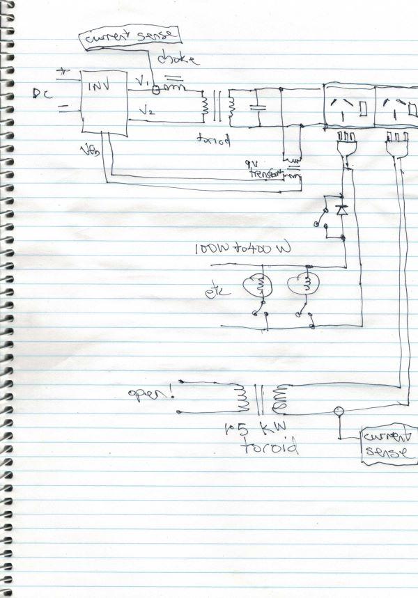
The work I've done with this seems to have sorted out the problem of applying unbalanced AC loads (i.e. those with some DC component) to the inverter. Symptoms include large current spikes in the primary winding of the toriod.
The code is robust and does not tend to uncontrolled oscillation and brings things back to an acceptable version of "normal".
See below for a drawing of the test setup.
I can switch in one or the other or both loads to see how the firmware performs.
One particular situation is dealt with poorly, in fact it tends to bad primary current spikes. This is when I have the DC load and the open ended toroid connected. The firmware does initially reduce the bad primary current spikes but then it goes bad again.
I think I now know what is happening.
The firmware reduces one of the inverter's output amplitude accordingly to minimise the current spike. This is seen in the main toriod which is exposed to the DC load. But the other toroid (not connected to anything and so has no load, not even a DC load) sees the unbalanced AC that the main toroid does. And so it progresses to saturation too.
In this configuration, with one toroid having a DC load and one not, there is no adjustment to AC amplitude balance that satisfies both.
After a few seconds the test settles to a state where both toroids have significant current spikes. The extra toroid, without a load, has only one current spike, while the main, load bearing tx has two, on each zero crossing.
This test configuration is not useful in my view since it does not simulate anything we do in the real world. So I do not care that the firmware performs poorly then.
I have tested the firmware with DC loads (i.e. leave the diode in circuit) from 100W to 1000W and it works really well.
Edited 2026-11-22 16:13 by poidawronger than a phone book full of wrong phone numbers
mab1 Senior Member Joined: 10/02/2015 Location: United KingdomPosts: 291
Posted: 11:40am 22 Nov 2026
Copy link to clipboard
Print this post
I'm not so sure this doesn't represent anything we do in the real world:- on my own system i have grid tie inverters such as a SMA SB1700 which is galvanically isolated by a 1.7kva toroidal transformer, and at the beginning and end of the day the transformer will be running, but with just a few watts of power going through it (also: does this effect only occur with an unloaded transformer? Have you verified that it doesn't occur when the transformer is partially or fully loaded?).
In my own case, my Wiseguy inverter sees transformer loads every day, (GTIs, mig welder, small transformer based psu's, etc) whereas it has never had to deal with a diode rectified load.
I've been watching this thread with interest, and i take my hat off to you for your hard work to make thebackshed inverters even better than they already are ; but whilst your mod should only kick in if a dc load is put on the inverter, if there are several (variously loaded) transformer loads connected at the time, I do wonder if this risks creating a bigger problem than the one it is solving?

 Notice. New forum software under development. It's going to miss a few functions and look a bit ugly for a while, but I'm working on it full time now as the old forum was too unstable. Couple days, all good. If you notice any issues, please contact me.


 Print this post


 ; but whilst your mod should only kick in if a dc load is put on the inverter, if there are several (variously loaded) transformer loads connected at the time, I do wonder if this risks creating a bigger problem than the one it is solving?