
|
|
Forum Index : Electronics : Inverter / PWM Controller problem
| Author | Message | ||||
Gill Senior Member Joined: 11/11/2006 Location: AustraliaPosts: 669 |
I have asked Selectronics to help with a problem I'm having, however they may just see a sale so would like some feedback from you fellas if anyone has thoughts/questions on it. G'day, My name is Gilxx xxxx and I bought a (then new)SPI 1200 i2SS S/No. 8446 many years ago. It had a repair at your service centre several years ago and it is still performing satisfactorily now, meeting all my general home power needs. With the knowledgeable, considerate and informative service I received then, I thought to seek your assistance with this inverter seemingly limiting other devices connection to the battery. I have built a PWM Controller with a data logging feature to complement my development of DIY wind and water power generation units. Unfortunately, in spite satisfactory bench testing, it does not perform to an acceptable standard when installed into my power system. The problem seems to stem from the power demands of the inverter with a rapidly fluctuating current and an associated fluctuation of battery voltage that worsens with increased power demands . This makes it near impossible for the controller to adjust to a relatively stable duty cycle or log usable data over a day. I have just had prior to fitting the PWM controller (which was promoted by) the successive failure of two Morningstar_ ProStar-30 Solar (PWM)Charge Controllers. In both cases failure was in the area of the solar input connection. To me this seems unrelated but worth a mention. In all cases NO HOMEMADE GENERATORS WERE CONNECTED, just solar panels. With the inverter turned off or in stand-by mode the logged data is stable. When a load is applied to the Selectronic inverter, logged data is erratic. If the Selectronic inverter is substituted with a DicKSmith el-cheap-o inverter, logged data is far less erratic. This pic shows the variations in logged data at night(No input,No load Dumping). Load = Fridge, 1x fluoro & laptop with fridge turning off. 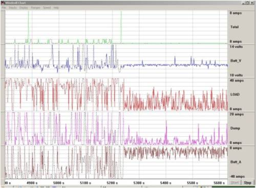
This pic shows comparison between the Selectronic and a Dick Smith Inverter: Some input(hydro is actually a second small solar array), load = laptop. Selectronic on left, DSE on right. 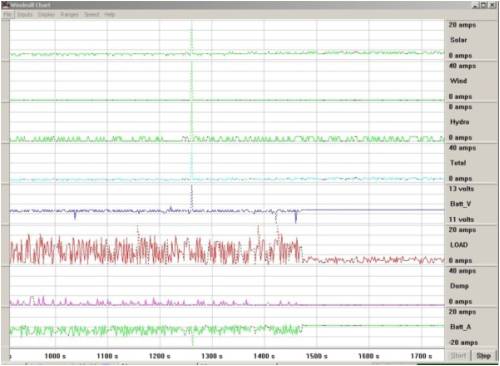
So could you please help. Does the inverter need repair? Can I make a filter or something to reduce/eliminate this effect? Must I update to a better design? Your feedback would be greatly appreciated. Sincerely Gill xxxx What I failed to emphasise was that at the voltages logged there is NO PWM at all as it is Boost Mode and PWM is not even running. After all, how could I apply PWM to to what is on the first chart? I'm in trouble.... Gill EDIT: Sorry for poor definition. Have tried to get larger 600 wide charts but it will not comply. Full size charts: 2008-05-19_145223_worry.zip Also that model inverter is a modified square wave, cause I know someone will want to put it all down to that.(see how I love my inverter) was working fine... til the smoke got out. Cheers Gill _Cairns, FNQ |
||||
| dazz Regular Member Joined: 15/04/2008 Location: Posts: 78 |
Hi Gill, The first thought that hit me when i saw those charts was electrical/rf noise produced by the inverter. It was just a thought based on previous experience with data logger applications. I have had some success removing such noise by placing the offending component into an earthed metal box and line filters to stop direct noise transmission and the lines being used as an rf antena for the noise. Or for similar shielding on the component picking up the noise cheers, Daryl |
||||
| Gill Senior Member Joined: 11/11/2006 Location: AustraliaPosts: 669 |
Wow! They did get back to me fast. "Telstra could take a lesson from that kind of service" So here's their reply: Hi Gilxx, My immediate thoughts are that there are a few possibilities. Firstly the interference may be simply inherent in the square wave circuitry, unfortunately we do not have an SPI unit in service to test. Secondly ,considering the age of the unit, the capacitors across the output stage may be seriously dried out and allowing increased ripple current across the battery. Factors that may make this problem worse would include excessive separation of the battery cables (ie greater than 30mm), the length of the battery cables and the condition of the battery pack. In short, anything that increases the impedance of the battery, cable and mosfet switching inductive loop will increase ripple current and, therefore, the amount of interference apparent on other parts of the circuit. Irrespective of it�s effect on the interference I would consider changing the caps as excessive deterioration will increase the ripple current until it causes fet failure � a fault that is generally not considered economically viable. Hope this helps. Regards, Rob xxxx Product Support Engineer Mmmmm, sounds like some improvement is possible then. I bet those caps are huge expensive suckers though. Ah well, it's only money. was working fine... til the smoke got out. Cheers Gill _Cairns, FNQ |
||||
| Gill Senior Member Joined: 11/11/2006 Location: AustraliaPosts: 669 |
Thanks dazz, I think you have a valid point. There was a time when I bought a sine wave inverter as the square wave would cause the oscilloscope trace to spike at every switching and that is 4 times per cycle x 50 per sec, so you can imagine how annoying that is. However the U-bute, no RFI, Supa-Dupa sine wave had so many harmonics that added to whatever I was measuring it was totally unusable. Further to that, RFI was so bad several ham bands were interfered with, some badly, and all this from an inverter 13 meters away, shielded by 2 metal walls, on an independent power supply with nothing plugged in and therefor under no load. You can see why I don't lap up the recommendations to go sine again. I didn't think my installation was too bad but maybe I need to go anal over RFI filtering as well. It can't hurt I guess. thanks  was working fine... til the smoke got out. Cheers Gill _Cairns, FNQ |
||||
| dazz Regular Member Joined: 15/04/2008 Location: Posts: 78 |
well at the very least, playing with some shielding and filtering might buy you some time and cost, before those humungous caps really go. It's sad I know, but sometimes you just have to let go of old equipment  But don't forget to tell yourself, "well it had a good life" But don't forget to tell yourself, "well it had a good life"
At least thats how I try to reconcile the situation  |
||||
herbnz Senior Member Joined: 18/02/2007 Location: New ZealandPosts: 258 |
Hi Gill I use a Trace DR series same vintage likely , it also shows interferance like yours. My gut feeling is it is the designs of the time and capacitors are ok. Do you get a crack when connecting inverter thats caps chargingif so likely ok. However lots old equipment have large caps get some , you only need up to 50v , 10000uf say connect across batteries in addition cannot do any harm. Re modified to sine wave I to like my old unit only negative is noisy induction motors . Nowdays I likely would buy Sinewave but then the price diff to great. Herb |
||||
oztules Guru Joined: 26/07/2007 Location: AustraliaPosts: 1686 |
Gill, Have you looked at the battery terminals with a scope to see if the ripple is actually there, as an emf ripple (due to the duty cycle of the pushpull stage). If some ripple is noticeable, then perhaps a brutal choke may help, or the caps may be down a bit. The elcheapo inverter may run at a higher freq in order to save on transformer bulk, and this may help explain the lower hash (smaller bites of current more often with new caps and easier to filter at higher freqs). In other words, is your logger logging actual instantaneous peaks, or getting rfi into it's input.... maybe freq chokes here too. Don't know enough about your logger to be of any more sense (if any) ......oztules Village idiot...or... just another hack out of his depth |
||||
| Gill Senior Member Joined: 11/11/2006 Location: AustraliaPosts: 669 |
Thanks oztules, I've had to put further investigation on hold at the moment, but appreciate your input. I'll scope the battery under various loads as you say and see how that compares with logger readings.  was working fine... til the smoke got out. Cheers Gill _Cairns, FNQ |
||||
