
|
|
Forum Index : Electronics : Relays: Carbon contact refurbish
| Author | Message | ||||
Chopperp Guru Joined: 03/01/2018 Location: AustraliaPosts: 1032 |
@bigmik My carbon rods were posted Thurs & according to the tracking they are in Noosaville, which is north of Brizzy, a long way from Toowoomba. Be interesting to see if they get any further on Monday. We will have 400mm of rod to play with, so plenty to experiment with. Should be interesting. BTW, these contacts don't normally go "Klunk" or "pound" like a normal relay. They just "vibrate" gently on & off around their operating point, but I get your point. On initial start & stop they may do this. ChopperP |
||||
| Chopperp Guru Joined: 03/01/2018 Location: AustraliaPosts: 1032 |
Rods arrived this morning. Well packaged in a solid PVC tube & bubble wrap. I didn't realise they were sent from Noosaville, not Brizzy  . Still didn't get into Toowoomba until 4am this morning. . Still didn't get into Toowoomba until 4am this morning. Appear to be about the same hardness as what's on the contacts, maybe a tad softer. Now the fun begins.... 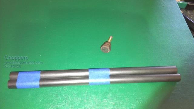 ChopperP |
||||
| Chopperp Guru Joined: 03/01/2018 Location: AustraliaPosts: 1032 |
Success!!! We machined the rod down until it was just bigger than the well in the bolt head. We then put a bit of a bevel on the end The bolt was then placed in the tail stock of the lathe & we gently forced the head onto the rod. The rod was then cut off. With the rod out of the chuck, we used the tail stock again to force the carbon right into the head. It aint coming out. Two were done today, 8 more to do (includes a couple of spares). Many thanks to all who contributed to this exercise. I'll post some piccies of the contacts in situ. 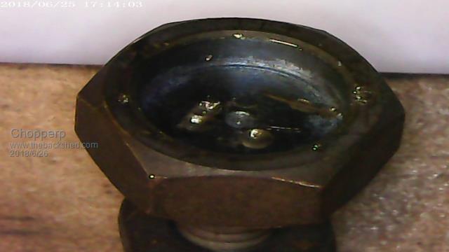 Old pad removed from the head. Couple of drill pot holes there. 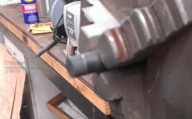 Blurry photo of the rod after being machined 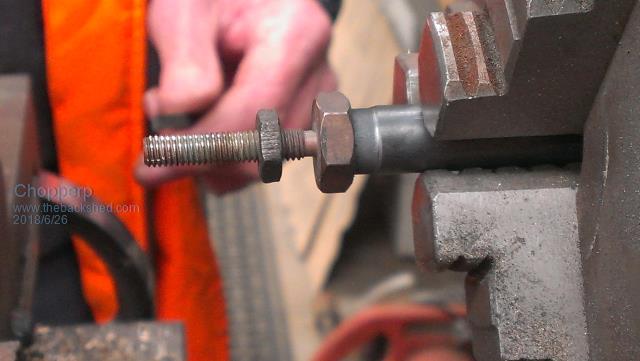 Bolt pushed onto the rod 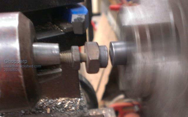 Bolt loosely held in the chuck while the rod was cut 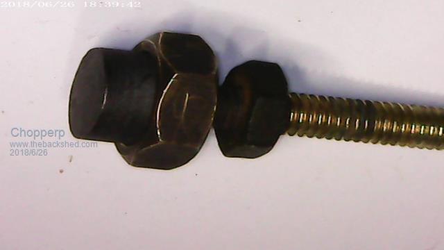 Finished item ChopperP |
||||
bigmik Guru Joined: 20/06/2011 Location: AustraliaPosts: 2870 |
Looks great, I really thought the rod would shatter under pressure , hence suggesting heating the head, but I am impressed.. They look great.. Regards, Mick Mick's uMite Stuff can be found >>> HERE (Kindly hosted by Dontronics) <<< |
||||
| Warpspeed Guru Joined: 09/08/2007 Location: AustraliaPosts: 4406 |
I am double impressed ! Very nice work Chopper. Cheers, �Tony. |
||||
| Chopperp Guru Joined: 03/01/2018 Location: AustraliaPosts: 1032 |
Thanks guys for the comments. Pushing the bolts onto the machine rod was an experiment which did work. ChopperP |
||||
| johnmc Senior Member Joined: 21/01/2011 Location: AustraliaPosts: 282 |
Well done Chopper. It does look on the top picture of the machined brass head , That the brass head has been upset by some pressure after the carbon rod was inserted. Cheers john johnmc |
||||
| Chopperp Guru Joined: 03/01/2018 Location: AustraliaPosts: 1032 |
Hi Johnmc Thanks. One of them was slightly bent. I think that this was a pre-existing condition. Not a major problem. Contacts fitted. Ready for testing tomorrow. ChopperP |
||||
| Chopperp Guru Joined: 03/01/2018 Location: AustraliaPosts: 1032 |
Removed the old contacts & installed the refurbished ones in the current limiting relay. Gave the pads a bit of a 'polish' & set the gaps to the required 25 thou with the armature roughly horizontal. Connected my test set up & at just over the required 31A, the bottom contact opened & hovered between the top & bottom contacts. In operation, this will cause about a 75% drop in the generator's field current, reducing it's output. At 33A, the top contact fully closed. When this happens, the field current is totally inhibited, cutting the output altogether. The reverse occurred when the current was reduced. This is how I had it set up with the original contacts. Good that things stayed the same. The current is set by the armature return spring tension & the differential (hysteresis) by the vertical position of the contacts. Much fun. In normal current limiting operation, the relay will 'work' mainly on the top contact. Some piccies below FYI. The set of contacts in the background to the right are for the voltage regulation. They're next to be done. 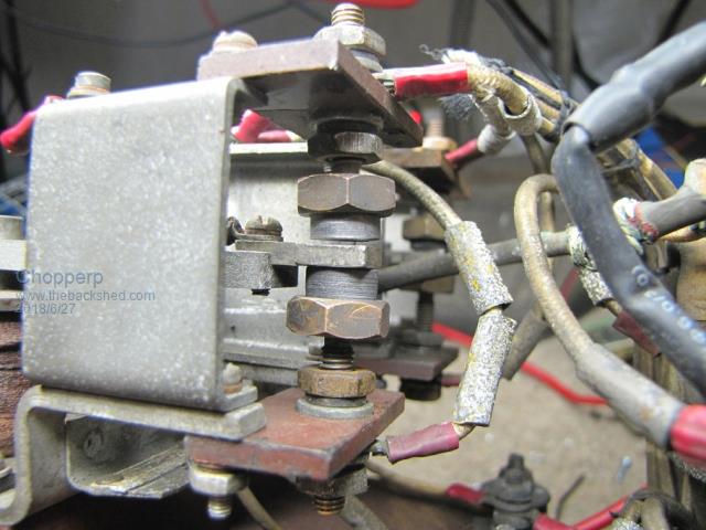 Contacts in the 'Rest' position. Current below 31A 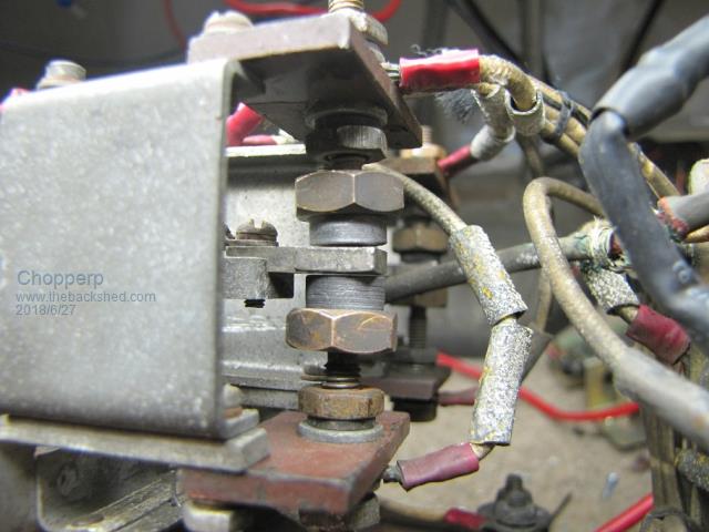 Current at about 31.5A. The armature sits between the two contacts. 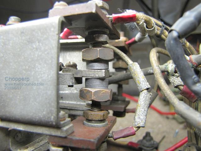 Current at 33A. Top contact closed. 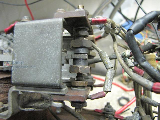 Current just above 31.5A. Some arcing evident on bottom contact ChopperP |
||||
Madness Guru Joined: 08/10/2011 Location: AustraliaPosts: 2498 |
Some people settle for a model train track in the garage but you take it up a few notches from there!  There are only 10 types of people in the world: those who understand binary, and those who don't. |
||||
Revlac Guru Joined: 31/12/2016 Location: AustraliaPosts: 961 |
That looks like a proper job there. Chopperp  It would last for many more years of service.  Wonder what the next job might be? Cheers Aaron Off The Grid |
||||
| Chopperp Guru Joined: 03/01/2018 Location: AustraliaPosts: 1032 |
@Madness: Yeh, tell me about it.  . Keeps me occupied & socialised though. Been a fun post. . Keeps me occupied & socialised though. Been a fun post.@Revlac. Thanks. Should last a good while. Still more contacts to do yet. This & another regulator to fully set up & test. Plus I also have a solid state version which needs further testing & probably refining to see if that is a viable alternative to these monsters. ChopperP |
||||
| Chopperp Guru Joined: 03/01/2018 Location: AustraliaPosts: 1032 |
I finally got around to testing the regulator in the Loco. I couldn't quite get some of the voltage regulation specs listed in the instructions on the bench so I sort of left it at that. No immediate need for it. We will now need it for checking the Loco in came out of next week at another location so it required a real test. I fitted it to our working Loco & got a qualified off-sider to fire the Loco up for me. Happy to say that it worked quite well. The idle charge current was not quite as high as the one it replaced but it came up & limited to about the 33A limit with the engine revved up a bit & stayed there while the voltage was low. The voltage steadily rose & started regulating a bit below 70V (cover on) with the current dropping of course. Slight adjustment needed to bring it up to around 70V. The regulators were swapped back again after the test. I still have to replace the carbon contacts & do a full setup on the main unit. Two spare old contacts have gone AWOL so I won't be able to do a direct replacement of the 4 contacts. Also, we will have to make up another cover as one is missing. Some photos. 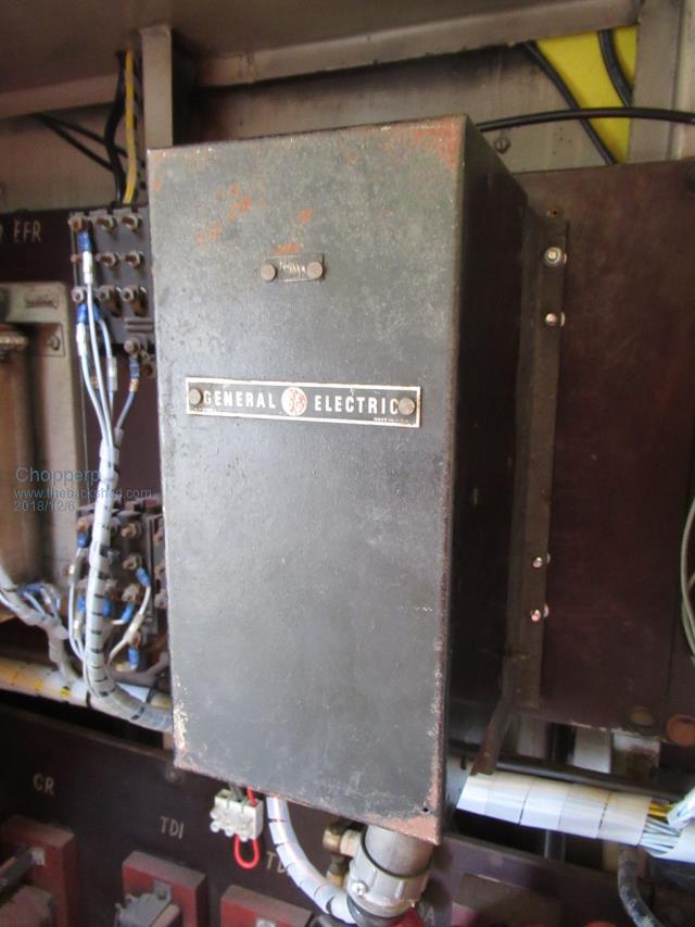 Regulator: Temporally Mounted with Cover 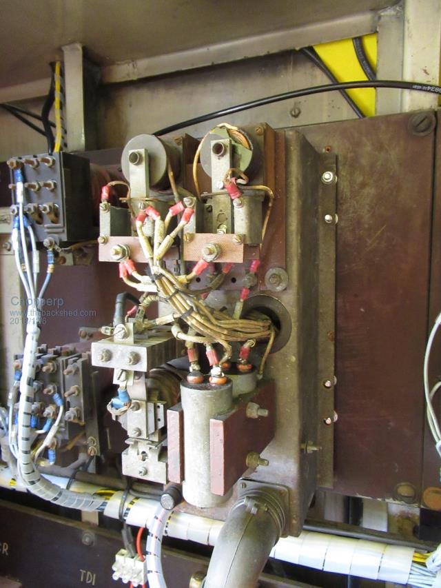 Regulator: Cover Removed RHS 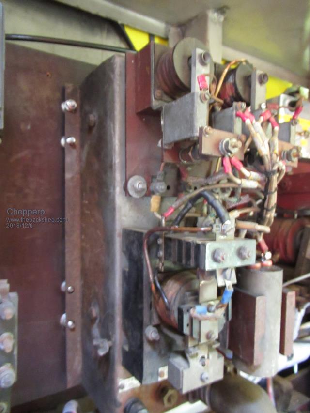 Regulator: Cover removed LHS 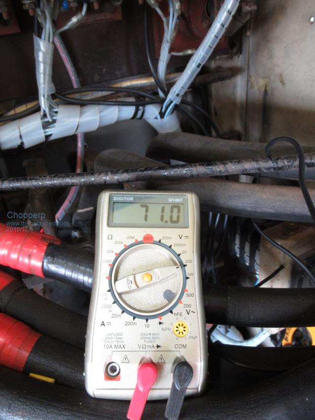 Output Voltage with Cover Removed. (Drops when cover fitted) 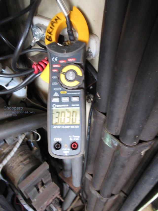 Output Current Falling from 33A Max. (Voltage Regulator Operating) ChopperP |
||||
| Chopperp Guru Joined: 03/01/2018 Location: AustraliaPosts: 1032 |
A follow up question from this exercise last year with the diesel loco's generator regulator. I'm just wondering how smooth would the output current be when it is current and or voltage limiting? I couldn't get much sense from searching Mr Google. I'm don't really know how much the inductance of the field coil and other factors would smooth out the on-off current pulses. The reason I ask is that we managed to boil the batteries dry & thus they are stuffed; (Bad maintenance on our part obviously & we did sort of think they were maintenance free to a certain extent) & we would like to know why they did lose all their electrolyte. I don't think over voltage charging was the reason. The trickle charger used was set for about 70V & limited to less than 4A & mostly ran at a lower current. I was thinking that maybe the pulsing nature of the charging current from the generator when running may have contributed to their demise. We are getting 5 of these which are similar to the dead ones. Reading some of the stuff on the website suggests that the charging ripple voltage should be in the mV range for good life. I don't particularly want to put the new set in if the charging current pulses are in the order of 50+ amps or so (30A average) These batteries aren't exactly cheap & probably are only just suitable for the job. The original Loco batteries were much bigger physically & in capacity & hellishly more expensive. Any thoughts please? ChopperP |
||||
