
|
|
Forum Index : Electronics : buck converter for mppt
| Page 1 of 2 |
|||||
| Author | Message | ||||
| poida Guru Joined: 02/02/2017 Location: AustraliaPosts: 1480 |
So I was thinking I want to put a mppt controller on the new 3kW array I added to the house. I already have 3kW on the car port roof, the new array is East facing on the gabled tiled roof. The problem is I no longer trust commercial solar power electronics to do anything except from cost a lot of $$ and maybe work up to the end of the warranty period. Cheaper stuff may never work at all. This leads me to making a mppt controller myself. Easy, really, they are a DC-DC converter with a bit of brains. I can do the brains bit no worries via an Arduino. The DC-DC converter needs to be efficient and strong. I present here my strong DC-DC converter. It's based on a broken inverter board, only using one 1/2 of the bridge. 5 x HY1906 per leg of the bridge. Talk about low Rds(on). Vds is only 65V and that is a problem since the array is wired in 2S so I get about 78V open circuit. No worries, this is just a proof of concept. I have some 3300uF 90V caps from the broken Victron inverter, so I used a few of them, 4 on the input, 2 on the output. I drive the mosfets from an IR21844 1/2 bridge driver, 400ns dead time. The gate driver IC is driven by an Arduino with a 20kHz PWM, 0-100% via a potentiometer. I have a home brew constant current load, based on a pair of mosfets I pulled out of a dead plasma TV, a PC cpu heatsink and a LM358 op amp. This load is good to 150W or more at 5A with large DC volts headroom. Operating conditions are: 30.0 V, 1.02 A DC in 10.00 V, 3.00 A out. The conversion efficiency is absolutely insane. (10.00 x 3.00)/(30.0 x 1.02) = 98 % It should come as no surprise that the mosfets remain stone cold. This will do the trick. The first limit to explore is the saturation of the inductor but for my needs I only need to deal with about 20A. What a success. Here is the setup. 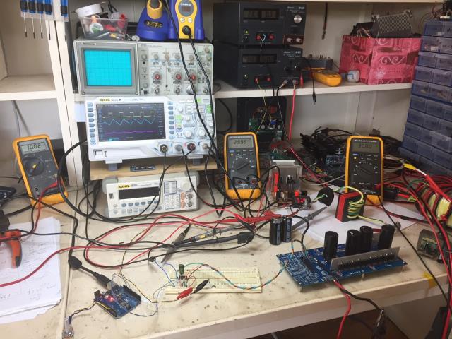 You can see the DSO recording the PWM, inductor current and output DC ripple. The ripple is only about 100mV. The inductor current trace shows nice straight lines which means no saturation. wronger than a phone book full of wrong phone numbers |
||||
| Warpspeed Guru Joined: 09/08/2007 Location: AustraliaPosts: 4406 |
Great stuff Poida. A software driven buck converter is not that difficult to do, only two potential traps to be aware of. An actively driven half bridge will always self start, but a conventional buck regulator with mosfet and catch diode combination may not, if it uses a voltage pump to power the upper mosfet gate drive circuit. If used to charge a battery, a buck converter with active lower device can work backwards as a boost converter powering the solar panel circuit from the battery. Not really a problem, unless the duty cycle becomes extreme then the reverse generated "boost" voltage can go extremely high and destroy things quite easily. None of this is a problem, unless you are not expecting it to happen. I am sure you already know all of this, but others here might get caught. I sure was.... Cheers, ĀTony. |
||||
| poida Guru Joined: 02/02/2017 Location: AustraliaPosts: 1480 |
Thanks Warpspeed My first thoughts on this are to get some decent conversion efficiency at low current, and expect efficiency to fall as current increases to my working levels of about 20A. Oh, and make it so it does not blow up with big current loads. I understand the synchronous buck is a Jeckel and Hyde thing where you can have a great working boost converter if Vin < Vout. The gate drive IC has a shutdown pin, which will be driven by the microcontroller, enabling output only when Vin > Vout by some reasonable amount. Shutdown, when active (logic High), lets the low and high side gates go high impedance so with a 10K resistor on the gate, they go to zero and stay there. A 1/2 bridge with both high and low gates pulled to zero will not switch at all. My basic microcontroller code will loop, checking if Vin > Vout, Vout < batt set point, Iout (current) less than system max, and search to maximise Iout by varying duty cycle. Shut down the gate drive when needed, back off duty cycle to maintain batt voltage..etc. I could not care less about the panel's maximum power, I only ever care about battery charge current. wronger than a phone book full of wrong phone numbers |
||||
renewableMark Guru Joined: 09/12/2017 Location: AustraliaPosts: 1679 |
It really is amazing how crap the commercial stuff seems to be. I know Oz has heard a lot of bad feedback from the units cased in blue as well. I dropped a dead Latronics inverter off to Warp the other day, he said it was designed poorly and a terrible dog to work on, but he fixed it with just a few dollars of parts. (thanks mate, I'll be in touch to pick it up) Yeah they seem to be designed to just work till warranty..... bastards. Do you plan to sell boards/kits? Cheers Caveman Mark Off grid eastern Melb |
||||
| Warpspeed Guru Joined: 09/08/2007 Location: AustraliaPosts: 4406 |
Yup, no sweat at all with a microcontroller directing the fun. The synchronous buck thing is certainly going to be more efficient, especially at lower battery voltages and higher charging currents which is how most people go about this. My own 100v battery charging system runs at only 10 amps maximum and usually less, so an ordinary fast recovery diode and one of those postage stamp sized isolated supplies powers the gate driver. My battery charger only charges the battery, it does not have to supply power to the inverter during the day, the inverter runs direct from solar voltage during the day. The battery gets a long slow continuous charge free from any discharges except on the very worst full cloud days. If you work it all out, the solar voltage is never going to be that much higher than the battery voltage, so the mosfet's duty cycle is always going to be very high, and the diode or lower mosfet hardly does any work at all. In my case the mosfet duty cycle will be 75% to 100% so the diode never sees more than a 2.5 amp average maximum, diode losses are very low. Ten amps going into a 100v battery is 1Kw The diode might eat up 2.5 watts of that (or less). Its just not worth worrying about and a diode solves the Jekyll/Hyde mosfets popping from over voltage problem. Mark, The problem with that grid tie inverter is that the circuit board, guts, and mosfets are inaccessible to do any real testing measurement, or fault diagnosis. Its a real bastard to take apart too, difficult to reach nightmare self tapping screws, and when its in bits it's not possible to run it. So it becomes just about impossible to fix unless you have some kind of factory test jig to test the main circuit board right out of the inverter. We were just lucky this time it was a simple obvious problem. Any fault more subtle or difficult to find may not really be practical to repair. Anyhow let me know when you plan to be down this way again, its a fair hike... Cheers, ĀTony. |
||||
| poida Guru Joined: 02/02/2017 Location: AustraliaPosts: 1480 |
Since my aim is to get the best from the 12 panels on the house roof facing East, I thought I better do a bit of homework now. There is another 3kW array wired in 3S x 4P tilted and facing North, this gives me the majority of the energy to the system. The panels are Topsola 250W TSM60-156P poly. I wire them 2 in series and have 6 of this in parallel. My battery is 48V lead acid. The manufacturer's specs give I/V curves for various illumination power levels. I want power/Voltage curves. I used https://automeris.io/WebPlotDigitizer/ to give me data points of the I/V curve, used Excel to give me power and plotted the power/Volts curve myself. I/V 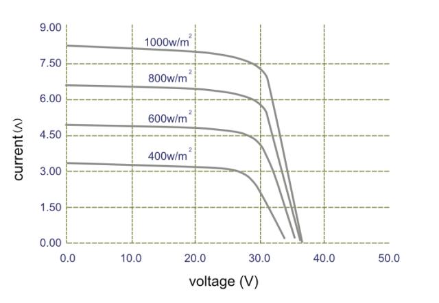 Today I was seeing current levels of 10 to 16A from this array with a battery voltage of 52 V. This means up to 2 A per 2 panel pair. So I use the 400W curve supplied since that is near enough. P/V 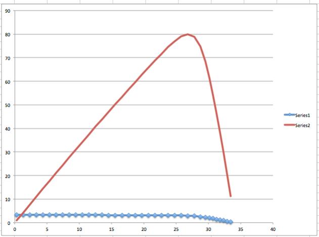 From the raw data I see max power voltage (for this illumination) is 26.78V or when 2 panels in series then it's 53.56V at 79.8W. At 26V, the power is about 78.5W The best I could ever achieve with mppt is to go from 78.5W to 79.8W per panel. That is a 1.6% increase. The only reason I put this extra array on the roof was to get something more from cloudy days, which we have in abundance here in Melbourne. Power levels under cloudy skies are of the order of 400W/m2 illumination or 78W per panel. So I conclude mppt is of no use for me with my 3kW array under Melbourne cloudy skies when I wire the panels in 2S x 6P and feed it into a 48V battery at a high state of charge. I finish this mppt investigation here. It was a nice idea but I don't need it. Mark: I am thinking of making a shield for the Arduino that has 2 socketed IR21844 gate drivers, 5V reg, output setpoint trim pot, feedback voltage divider trim pot with low pass filtering all powered by 12 DC (12 - 15V probably OK). This would make an excellent inverter or DC-DC converter controller. I would make it with point to point wiring first, see if it's any good and if so, engage someone to make a circuit board for me. I'm too old to learn PC board design. wronger than a phone book full of wrong phone numbers |
||||
zaphod Regular Member Joined: 03/06/2018 Location: United KingdomPosts: 93 |
Hi Poida, I would not be so quick to dismiss MPPT particuarly in cloudy places like Melbourne for you and UK for me! Except in high summer & blue skies my array spends a lot of time well under 400W/m2 and today for example has spent most of it around 70-100 with a peak of 200. Combine this with temperature effects and your battery state and it is very easy to fall off that rather sharp right edge of the power curve and end up with nothing particuarly at the beginning and end of the day. As winter advances the proportion of time spent at marginal power increases. Of course having built and programmed an MPPT controller I am a supporter and I agree there may be places like the Sahara where one would be wasted and also there are a lot of rubbish controllers that claim to be MPPT but are simply constant voltage etc etc. After 2 years of PV experience I say go for it but dont ever buy a commercial one :) Even on a very cloudy day like today I have done over 0.8Kwh/Kw installed and it's not dark yet! I have seen it follow the dusk down to 1W/Kw installed before it gives up :) PS here is one of my panel simulations to give you an idea of what happens below 400W/m2 (this is four 60 cell panels in series at 25C in 100W/m2 increments) 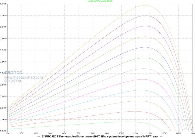 Cheers Roger 1Kwp DIY PV + Woodburner + Rainwater scavanger :) |
||||
| Warpspeed Guru Joined: 09/08/2007 Location: AustraliaPosts: 4406 |
That is pretty much what I have, four 24v panels in series per string. With a 100v (30 Winston cells) lithium battery and NO mppt in my controller. Using your curves which look to be about right. In a clear blue sky the optimum solar panel voltage would be about 115v. In dismal grey total cloud, the optimum panel voltage might be about 105v I concur with Poida, that a fancy software mppt controller is of rather limited value if you have carefully matched your battery voltage requirement to your panels. But you will never know for sure unless you do the test and crunch the numbers. As I have 5Kw+ of panels, or about 40 prospective amps ? taking ten amps or less of that for the charger is rarely ever a problem. A super smart software mppt might only take 9 or 9.5 amps to charge the battery at 10 amps, but that slight improvement would go completely unnoticed as there is almost always a power surplus available for charging. I worked all this out, not from simulations but actual measurement of the panels I planned to use. I used a Turnigy power meter and a continuously adjustable load of a big electrolytic and a pair of parallel 9 ohm radiator bars that discharged the electrolytic at an adjustable duty cycle. After seeing how constant the peak power voltage really is, even under extreme conditions, I decided to just overpower the system with a few extra panels and not bother about any slight loss from voltage mis matching. 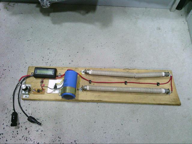 Cheers, ĀTony. |
||||
| zaphod Regular Member Joined: 03/06/2018 Location: United KingdomPosts: 93 |
Hello I should have mentioned my load is a 3Kw/240V water heater so needs a convertor anyway, buck & boost combined!! The curves I presented are only a rough match to the panels and do not account for the fairly high negative temperature co-efficient that sweeps the voltage up and down a fair bit as the sun goes in and out and the load goes up and down. Everybody has different opinions about MPPT it's a bit like the micro-converter debate and I am perfectly willing to admit the differance probably isn't large compared to a well tuned alternative. I did do lots of real physical measurements too, the simulation was mostly used to develop the hardware used in the heater converter and compare the effect of simply strapping the heater directly across the panels (awfull). I should have kept my comments to myself as my installation has no batteries....sorry Cheers Roger 1Kwp DIY PV + Woodburner + Rainwater scavanger :) |
||||
| Warpspeed Guru Joined: 09/08/2007 Location: AustraliaPosts: 4406 |
MPPT is excellent for absolute maximum efficiency where the solar panel area is very restricted, for example on a boat or camper van. No argument at all about that. For a domestic situation, solar panels are now becoming so cheap that its becoming more practical to just overpower a system with extra panels, rather than try to get the last 1% out of it. The loss due to mismatching might realistically be 10% to 20% maximum, and you can probably get that back and more by adding just one or two extra solar panels at fairly low cost. There is no one single correct answer to all of this. Cheers, ĀTony. |
||||
| Solar Mike Guru Joined: 08/02/2015 Location: New ZealandPosts: 1228 |
I have a job coming up this summer installing approx 5KW PV atop a group of containers in a remote paddock, we are using 50 volt bank of Lead-Carbon batteries float voltage approx 56.8 volts. Will be using 270W panels Vmp = 31.5V Imp = 8.57 amps, I looked at using groups of 2s by 2p to give me 63v @17 amps with 10 meter cable run (20m total length) back to the combiner box; on the surface this looks like an ideal match and a simple pwm controller can be used. However if those metrics are plugged into a PV panel loss Calc then using standard 4mm cable, each group would have a DC loss of 6%. As this setup will be audited to be signed off, it wouldn't pass NZ regs of max cable losses of 3% (means if there was a fire etc, Insurance wouldn't pay up), to get around this I would have to have groups of 2s PV panels per cable run, that's 10 cable runs, even using more expensive 6mm would still have 4% loss and not meet spec; add to that 10 lots of circuit breakers and 100m cable. So my reasoning to go mppt, there I can use 2 groups of 5s by 2p panels 157v @ 17a, so only 2 cable runs and 2.4% loss. Yes there will be some loss in the mppt controller, but is so much easier to setup than running heaps of cabling. As I'm building my own controller makes no difference really. If I was doing this at home, then yes simple pwm controller and chuck up a couple of extra panels to cover losses, as long it wasn't on the house roof, insurance wouldn't be affected. Cheers Mike |
||||
| hotwater Senior Member Joined: 29/08/2017 Location: United StatesPosts: 120 |
I'm getting lazy and everything is already probably being built. I have grid tie panels and use these $5 72V buck converters from China in parallel. They even come in a case with space for mods. It is easy to get them to operate autonomously at a power point voltage or drive them from an arduino. They even have their own opto isolator input. Saves hunting around for parts. They cqn easily operate MPPC which is constant voltage. I've run tests at the camp and in one season that power point doesn't change that much. 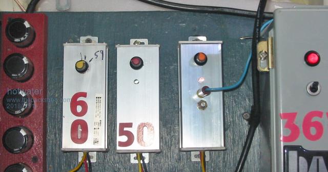 |
||||
| renewableMark Guru Joined: 09/12/2017 Location: AustraliaPosts: 1679 |
Mike with that calculator is the simple length in M take into account for the return cable? I put those figures through another calculator and it looks to me like it is allowing for the return. Mad showed me a great app for android phones, electrodroid, lots of handy stuff in that. So if you put in 10M it comes up with 3.03%. If you can shave 50cm off to 9.5m then it's 2.87% Or use 250w panels to get over the line. Cheers Caveman Mark Off grid eastern Melb |
||||
| Warpspeed Guru Joined: 09/08/2007 Location: AustraliaPosts: 4406 |
For all these types of calculations you only need to remember one number. .0172 That is the resistance of one metre of copper wire 1mm square area at 20 Celsius. Burn that number into your memory, its then dead easy to calculate voltage drops, and power loss for any length of any sized cable. Cheers, ĀTony. |
||||
| Solar Mike Guru Joined: 08/02/2015 Location: New ZealandPosts: 1228 |
That Calc doesn't specify return length. it says: L : simple lenght of the cable (distance between the source and the appliance), in meters (m). It uses resistance of .023, assuming max temperatures of 100c Using Warps 0.0172 value/M/M^2, (17a * 0.0172/4 *20m)/63 = 2.32% voltage drop which is 1/2 that of the Calc, so it is using L = there and back distance, ie 40m insteat of my input of 20m. So that changes things, even if the wire heats up somewhat, losses will be <3%, thus I can use 1 pair of cables per 4 panels, still 5 pairs or 10 total, but much simpler controller. |
||||
| Warpspeed Guru Joined: 09/08/2007 Location: AustraliaPosts: 4406 |
Great stuff Mike. Cheers, ĀTony. |
||||
| zaphod Regular Member Joined: 03/06/2018 Location: United KingdomPosts: 93 |
I beg to differ, first of all here in the UK panels are actually quite expensive to ordinary mortals AND in case you didn't know we tend to live in shoeboxes! So whilst I apreciate that to many members of sites such as anotherpower money and space is a none issue to some people it is. This is another reason I do not use batteries, they are VERY inificient and have a high cost both initial and write-off over time. I am fortunate that I am actually connected to the grid and have no fixed cost for so doing so the grid is my storage medium both for large loads and nightime. So the relative importance of MPPT depends who you are and how much money you have to spare and if you wish to get into CO2 saving not maximising your utelisation, the technical issue remains without doubt, more energy can be extracted using MPPT. Cheers Roger 1Kwp DIY PV + Woodburner + Rainwater scavanger :) |
||||
| Warpspeed Guru Joined: 09/08/2007 Location: AustraliaPosts: 4406 |
I was from the UK originally, and that is a very valid point. House blocks in Australia tend to be larger, with a much higher proportion of single story houses, which naturally provide much more roof area than in the UK. Its only in the inner suburbs of the larger cities where its now common to build tightly packed smaller two story home "units" as a result of sharply rising land prices. But in the outer suburbs and definitely "way out in the bush" space for a giant solar system is far less of a problem. Agree too that if you have grid power available, a storage battery is not cost effective, and probably never will be. I have run for almost three years without a battery, but am right now rebuilding my whole system to add 5Kwh of lithium cells. I am doing all this as a technical challenge and for fun rather than cold hard economic reasons. The cost of Chinese panels continue to slowly fall, and there is ready availability of very low cost secondhand panels here in oZ. So the situation here would appear to be very different to the UK as I remember it. A lot more sun here too. Cheers, ĀTony. |
||||
| nickskethisniks Guru Joined: 17/10/2017 Location: BelgiumPosts: 481 |
I was hoping You would continue this kind of testing. It's my plan to build something simular when I have more spare time. BTW, how come you don't have spike's (during current meassuring) during turn on and off from the mosfets? During my tests I got those nasty spikes, they went away when using snubber circuits over my diodes and Mosfet, I don't see snubbers. |
||||
| Warpspeed Guru Joined: 09/08/2007 Location: AustraliaPosts: 4406 |
There should not be any current spikes with a buck regulator, as long as the series choke has enough inductance. There must be a sufficiently large electrolytic at the buck regulator input, especially if fed direct from solar panels. Cheers, ĀTony. |
||||
| Page 1 of 2 |
|||||
| The Back Shed's forum code is written, and hosted, in Australia. | © JAQ Software 2026 |
