
|
|
Forum Index : Electronics : Warpverter Simulator
| Author | Message | ||||
mackoffgrid Guru Joined: 13/03/2017 Location: AustraliaPosts: 460 |
The Warpverter Simulator pcb plugs into the rear connector of the Arduino Due. The output of DAC0 can be displayed on your Scope. Press the button and it will grab two frames (50Hz) and output the data from the SerialUSB. (60 Hz is no problem) The data is in 10 micro-Second intervals. Details of the project can be found at Warpverter Simulator Github 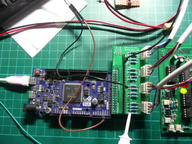 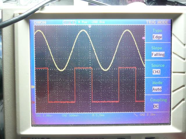 The PCB takes 4 pin molex connectors (suits me) and 3.81mm Pluggable terminal blocks to suit Tony's boards. Tony's Inverter board is in the bottom half of the photo - mine in the top half. 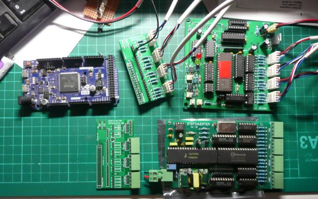 This is an example of the output data sent by the DUE. 2019-04-15_172702_Warpverter_Simulator_Serial_output.zip I need 2 pcbs and I'm sending Tony 2. The other 6 are up for grabs. Cheers Andrew |
||||
| poida Guru Joined: 02/02/2017 Location: AustraliaPosts: 1480 |
This looks excellent work. I'm sure it will help us develop a fuller understanding of the mysteries of Warp's creation. wronger than a phone book full of wrong phone numbers |
||||
| Warpspeed Guru Joined: 09/08/2007 Location: AustraliaPosts: 4406 |
This is an absolute must have for anyone planning to software-ise a Warpverter. The raw gate drive waveforms by themselves are not really recognisable as a sinewave without having four real bridge inverters, driving four real transformers to combine all the voltage steps at their correct amplitudes and in their correct polarities into a final built up sine wave. This handy little gadget uses a lookup table to convert the 81 possible mosfet gate drive combinations into an analog output that simulates what a real hardware Warpverter is going to do. Its very convenient to test and debug programming ideas without needing all the mosfets, heat sinks, electrolytics, and large transformers to monitor the output waveshape and amplitude. Watch the amplitude seamlessly increase and decrease over a 2:1 voltage range with very low harmonic distortion. And by just plugging in one or more inverter outputs individually in various combinations, you can see how the output waveform progresses from a crude high power rectangular wave, through to a stepped sine wave with ever finer steps and lower distortion. Cheers, ĀTony. |
||||
| mackoffgrid Guru Joined: 13/03/2017 Location: AustraliaPosts: 460 |
I'm running up the stm32_Warpverter at the moment and feeding it into the simulator. I could notice a little asymmetry at the bottom of the cycle. Feeding the frame data into GNUplot showed it up very well. 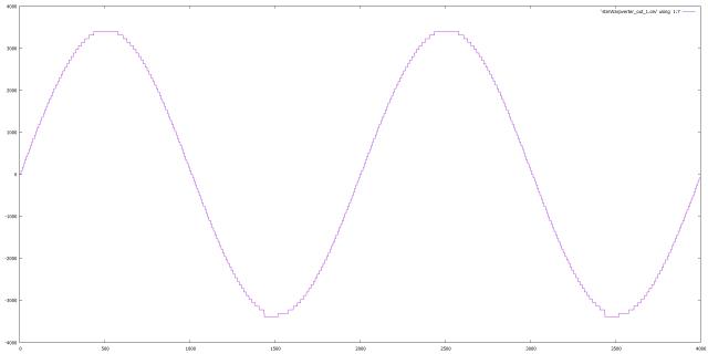 Then I loaded the data from both the eprom based inverter and the stm32_Warpverter onto the one chart. 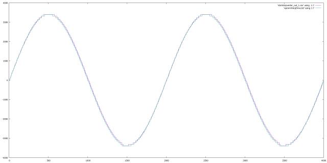 I spent many hours with a logic analyser when I wrote the software to generate the Eprom I use. This is much better  I tried to use OpenOffice Calc charting but I just could not get it right. I don't want to install MS office. I will use calc to look for DC bias and calculate Distortion, it'd be nice to use the chart as well. I'll run Tony's Inverter board into the simulator and we'll get another comparison. To see the images better you'll need to download the zip file. 2019-04-17_121525_Eprom_vs_Stm.zip Cheers Andrew |
||||
| Warpspeed Guru Joined: 09/08/2007 Location: AustraliaPosts: 4406 |
To measure my distortion I used an ancient HP333A distortion analyser. That is an analog instrument that subtracts the fundamental with a very deep tunable notch filter, and anything remaining is just the harmonic distortion (+noise). The 333A has an output on the back which is the residual distortion, and you can clearly see on an oscilloscope how much every single step deviates from what should be a perfect sine wave. Its the ideal tool for locating and fixing the largest lookup table errors. I generated my mathematical sine wave as just one ninety degree quadrant, then fitted four of those together to create a full 360 degree sine wave. It was not easy to match up the zero crossings and the peaks, but at least any errors end up being symmetrical. Total harmonic distortion figures I was measuring were about 0.85% with the full 81 steps at minimum dc input voltage, and about 1.8% with half the number of steps at maximum dc input voltage. On a spectrum analyser each of the harmonics were all below -40db falling away below that at higher harmonics. Cheers, ĀTony. |
||||
| Warpspeed Guru Joined: 09/08/2007 Location: AustraliaPosts: 4406 |
These minor discrepancies are not going to make any noticeable difference in a real world inverter. Its only really like a small pimple on an elephants bum ! The overall shape, and the area under the curve is what really counts. I cheated and scrolled through my 256 lookup tables and hand corrected any obvious lumps in any particular lookup table, and only the really worst ones were fixed. My programming skills are just not up to the job of writing a clever program to do the whole thing in real time and get it absolutely perfect. That is one of the big advantage of the multiple lookup table approach. Many sins can be painted over with some manual editing. And a direct lookup table is very fast to access, much faster than trying to crunch numbers in real time for every single step over and over again. Cheers, ĀTony. |
||||
| mackoffgrid Guru Joined: 13/03/2017 Location: AustraliaPosts: 460 |
You're right. These little discrepancies are probably negligible compared to both, the area under the curve (its what counts), and what we do after it leaves the processor and into the world of real life electronics and transformers. Be that as it may, I changed my algorithm so it should be faster and more correct. The evidence. 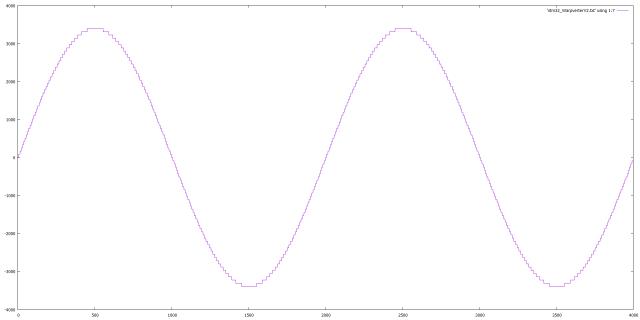 2019-04-17_142018_stm32_WarpverterV2.zip I'm happy with that. Cheers Andrew |
||||
| Warpspeed Guru Joined: 09/08/2007 Location: AustraliaPosts: 4406 |
Sheer perfection Andrew, well done ! This is a perfect demonstration of the usefulness of Andrew's simulator for anyone wishing to write their own from scratch Warpverter driver software. If care is taken with getting the transformer turns ratios as close as possible, it is just amazing how four simple square wave inverters can create such a perfect sine wave. Cheers, ĀTony. |
||||
| Tinker Guru Joined: 07/11/2007 Location: AustraliaPosts: 1904 |
So how close, in figures is as close as possible? Since we cannot do half turns on a toroid. Can you please show an example calculation how you would manipulate the figures from that online calculator you showed a link previously? I messed around with it, putting in approximate turn numbers for a given voltage until the result was close to one tesla. But its never exactly so, one turn more or less made a fair difference. Or am I going the wrong way about with this? Klaus |
||||
| Warpspeed Guru Joined: 09/08/2007 Location: AustraliaPosts: 4406 |
At minimum voltage the individual steps are just over eight volts. We are adding four independent voltages together to make those steps. How close, maybe +/- one volt might be a reasonable worst tolerance. If two windings were each 1v high (2v high together) and the other two 2v low together, we might have a four volt error. So we might jump four volts up to one step, then twelve volts up to the next step. That would probably be o/k, but if its much worse than that its going to less good than it might have been. Its quite possible to add or subtract turns to both primary and secondary until you reach some ratio that comes out very close, well within one volt. And its always better to add extra turns if you have the room to do it. I have some figures here for Marks transformers which require a 44v primary. Number 1 transformer 25 turns/128 turns, primary 44v x 128/25 = 225.28v (0.28v high) Number 2 transformer 61 turns/104 turns, primary 44v x 104/61 = 75.02v (0.02v high) Number 3 transformer 60 turns/34 turns, primary 44v x 34/60 = 24.93v (0.07v low) The third transformer is designed for a 400Va core I have here that I will give Mark. The flux density on the third core is high at 1.1 Tesla, but idling power becomes much less important with the smallest transformers. But getting the voltages closer to being exact is a much better tradeoff than reducing the flux density. I cannot remember what you are doing because you decided to start again from scratch. If you give me some core dimensions I will have a go at designing yours and see how the figures turn out. Cheers, ĀTony. |
||||
renewableMark Guru Joined: 09/12/2017 Location: AustraliaPosts: 1679 |
Hang on, don't I need 4 transformers? BTW you'll be getting a dans card for that torroid Warp.  Or I can swap you with a bigger one if it's of any use to you. I have a few 2kw's Cheers Caveman Mark Off grid eastern Melb |
||||
| Warpspeed Guru Joined: 09/08/2007 Location: AustraliaPosts: 4406 |
Mark used an old oZ inverter core that already had a 128 volt winding epoxied onto it, and it was extreme good fortune that adding a 25v primary worked out so very close. Lets look at some alternatives to that. Required ratio 44v/225v Primary 23 turns, closest secondary 23 x 225/44 = 117.6 turns Primary 24 turns, closest secondary 24 x 225/44 = 122.7 turns Primary 25 turns, closest secondary 25 x 225/44 = 127.8 turns 44v x 128/25 = 225.28v Primary 26 turns, closest secondary 26 x 225/44 = 132.9 turns 44v x 133/26 = 225.1v Primary 27 turns, closest secondary 27 x 225/44 = 138.1 turns 44v x 138/27 = 224.9v All very very close, but adding two extra turns of 35mm squared wire to the primary may have been a problem. Twenty five turns makes a perfect wire bundle 1 + 6 + 18 = 25. Adding two more turns of 35mm squared to the primary and five extra turns to the secondary would have hardly made any worthwhile improvement to the voltage error, but may have been just too much for the available hole size. Cheers, ĀTony. |
||||
| Warpspeed Guru Joined: 09/08/2007 Location: AustraliaPosts: 4406 |
I will put that 400 Va toriod in the mail ASAP, it will be a nice size for number three. Primary 60 turns 1.6mm squared two windings (in parallel) 17 amps. Secondary 34 turns 8mm squared on top 30 amps. When we get there with that, we can start thinking about number four. Cheers, ĀTony. |
||||
| Tinker Guru Joined: 07/11/2007 Location: AustraliaPosts: 1904 |
Thanks Tony, I'll take you up on that - my calculator is running hot trying to find the best ratio. What I'm after is minimum number of turns (obviously  ) and I'm still unclear about what influence to that a given minimum battery voltage has. ) and I'm still unclear about what influence to that a given minimum battery voltage has.A realistic figure for my battery is 48V. But if instead selecting 45V results in less turns then I'm all ears. So, my big core has a 6175mmsq cross section area. The hole is 85mm. I'll start with that as I'm still trying to find a matching core for #2 to get its 2205mmsq up to a more reasonable 4410mmsq. That one had a 90mm hole. #3 & 4 cores have not yet been acquired. Klaus |
||||
| Warpspeed Guru Joined: 09/08/2007 Location: AustraliaPosts: 4406 |
O/k Klaus, Minimum voltage 48v which is 3.0v per cell for x16 Winstons which is the end voltage I am using. 48 volts, 50Hz, core area 61.75cm squared, 1.0 Teslas = 35 turns. I tried it for 45v but it still comes out as 35 turns, not 34 turns so you gain nothing. Primary 35 turns x 225/48 = 164.06 turns. 48v x 164/35 = 224.91 volts. Hole size 85mm, circumference 267mm. 164 turns/267mm = 1.62mm. Its just not going to fit. Try 32 turn primary 150 turn secondary, that increases our flux to 1.09 Teslas still o/k. 48v x 150/32 = 225.0v exactly ! Now our circumference is 267mm and with luck about 165 turns might fit in theory onto a first layer, 159 onto a second layer, and 153 onto a third layer. The first two layers of 150 turns will go on very easily. The third is going to be real tight but should just be possible if you are mean, frugal, and stingy, with the mylar tape, and flatten out the first two layers within the hole.. There is almost no voltage between adjacent turns between layers anyway, so you do not need much additional insulation. 1.6mm wire is 2.0mm squared about 8 amps per layer. Three layers, 24 amps at 225v or 5.4 Kva. The primary will be 32 turns of 6mm x 150/32 = 28mm squared, or whatever comes closest to that size and fits the hole. Tycab sell a single insulated fine multi stranded cable 32mm squared might be the closest size. Cheers, ĀTony. |
||||
| Tinker Guru Joined: 07/11/2007 Location: AustraliaPosts: 1904 |
Thanks Tony, three layers of 1.6mm wire it is for the secondary. For the primary I plan 7 strand twisted 1.6mm wire = 14mmsq. Two x 32 turns makes exactly 28mmsq, that should fit (I hope ).Klaus |
||||
| The Back Shed's forum code is written, and hosted, in Australia. | © JAQ Software 2026 |
