
|
|
Forum Index : Electronics : stm32_Warpverter
| Author | Message | ||||
mackoffgrid Guru Joined: 13/03/2017 Location: AustraliaPosts: 460 |
This project has been a joy to work on. It's come along very well. All the resources can be found at stm32_Warpverter Github The PCB features the four Transformer outputs which take pluggable terminal blocks or molex connects - and are 100% compatible with Tony's Inverter or my Eprom based Inverter board. Other features include: INPUTS : Battery Voltage is sensed on board, Two thermistor inputs, ON input, OFF input, Current Sensor input (3 pin 5v,gnd,signal), Sync input, and 12V input in case the ACDC power supply is not installed. OUTPUTS : Four Transformer outputs, Two Fan controls, 50Hz pulse output (allows for Sync signal), Sync Relay control. SPARES : Pins on PCB to break out 2 more analog pins, 4 digital I/O, RX-TX port. 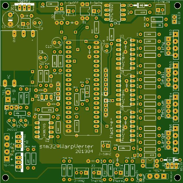 Forgive my messy bench. The Simulator has been invaluable. 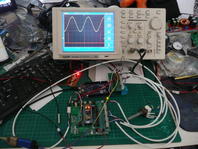 The software went through an evolutionary process. The Warpverter software makes extensive use of table look-ups. And why not, the basic BluePill has 64k flash Rom. Eventually I peeled the table building process away into another Arduino program. The Warpverter is fully functional. The ADC is fully implemented making use of the dual ADC of the BluePill. I have the DC voltage as the sole input to ADC2 and is running in continuous mode. All the other analog inputs are muxed, or using scan mode of the ADC and results are DMA'd into an array. Apart from setup, this happens automatically by the processor, without software intervention. Very cool. Features implemented : The Warpverter output modulates the output voltage with respect to Battery Voltage. Thermistor one and two controls Fan output one and two. Control can be PWM or Bang-Bang. Over Temperature Shut down for Thermistor one and Two. Under Voltage (Battery) shut down Off control: Quick response, suitable for fault sensors. On control : Much slower response. Guarantees Off - On cycles are longer than many 50Hz cycles. The MakeTable program runs on a BluePill and exports the tables to the Serial Monitor. This is Copied and pasted directly into "LookupTables" tab of the warpverter source code. An except of the MakeTables code where User Defines are set. /*------------------------------------------------------------------------------- * * USER DEFINED VALUES * * TIMER_OVERFLOW : Should either be * OVERFLOW_50HZ or OVERFLOW_60Hz * * NOMINAL_VAC : Whole integer value * - Is the output RMS AC value you expect AT the * nominal Battery Voltage. * * NOMINAL_BATTERY_VOLTAGE : Whole integer value * - Expressed in millivolts. * - This is the Battery Voltage for * which the transformers turns ratio * results in the Nominal RMS AC voltage. * * TRANSFORMER_COUNT : Number of transformers in Inverter. (Max 4) * * BATTERY_LOW_CUTOFF : Whole integer value * - Expressed in milliVolts * - Inverter will turn off at this level. * * BATTERY_VOLTAGE_AT_MAX_ADC : Whole integer value. * - Expressed in milliVolts. * - This is the Maximum Battery Voltage * value read by the ADC(analog to digital converter). * - Put another way. This is the Battery Voltage * that when divided down and feed into the ADC is 3.3 volts. * - Ensure 3.3volts is not exceeded or damage may result. * ---------------------------------------------------------------------------------*/ #define NOMINAL_VAC 240 #define NOMINAL_BATTERY_VOLTAGE 26500 // in milliVolts #define TRANSFORMER_COUNT 4 #define BATTERY_LOW_CUTOFF 24500 #define BATTERY_VOLTAGE_AT_MAX_ADC 35000 // milliVolts /*-------------------------------------------- * Manual Setting of Transformer Secondaries * - If zero - automatic settings are used. * - All should be zero or All should be set. * - Measure or determine Secondary Voltage * AT Nominal Battery Voltage. * - Settings should be in Volts x 10 * (ie. 235 volts should be 2350) ---------------------------------------------*/ #define TRANSFORMER_LARGE_SECVOLT 0 #define TRANSFORMER_MEDIUM_SECVOLT 0 #define TRANSFORMER_SMALL_SECVOLT 0 #define TRANSFORMER_TINY_SECVOLT 0 /*---------------------------------------------------------- * Fan Controlls * * ALL Temperatures are in degrees Celcius. * * Fans can be controlled by PWM or Bang-Bang. * - For Bang-Bang control, set FANx_ON_FULL with a lower number than * the FANx_ON_TEMP_START and it will use this as the Hysteresis value. * * FANx_ON_TEMP_START : Temperature where PWM control will start. * - In Bang-Bang mode Fan will be turned fully on * at this temperature. * * FANx_ON_TEMP_FULL : Temperature at which Fan is fully on. * - In Bang-Bang mode this value is the Hsteresis value. ------------------------------------------------------------ */ #define FAN1_ON_TEMP_START 35 #define FAN1_ON_TEMP_FULL 45 #define FAN2_ON_TEMP_START 45 #define FAN2_ON_TEMP_FULL 5 /*----------------------------------------------------------------------- * * TEMPERATURE_x_CUTOFF : Inverter will turn off at these Temperatures. * ------------------------------------------------------------------------*/ #define TEMPERATURE_1_CUTOFF 65 #define TEMPERATURE_2_CUTOFF 60 Regards Andrew |
||||
| Warpspeed Guru Joined: 09/08/2007 Location: AustraliaPosts: 4406 |
[quote] Features implemented : The Warpverter output modulates the output voltage with respect to Battery Voltage. Thermistor one and two controls Fan output one and two. Control can be PWM or Bang-Bang. Over Temperature Shut down for Thermistor one and Two. Under Voltage (Battery) shut down Off control: Quick response, suitable for fault sensors. On control : Much slower response. Guarantees Off - On cycles are longer than many 50Hz cycles. [/quote] Lovely stuff Andrew. That is all that is really needed for a fully functional inverter. I do my fan control with a 240v commercial temperature display/controller module, and a powerful centrifugal 240v air blower. A higher dc voltage system does not really lend itself to using low voltage fans. My undervoltage shutdown consists of an undervoltage disconnect at the battery. Software control of all this is a very big step forward. Really looking forward to trying this out on my own inverter. Cheers, ĀTony. |
||||
| mackoffgrid Guru Joined: 13/03/2017 Location: AustraliaPosts: 460 |
Tony, as soon as my plug-in terminal blocks come I'll send you a board. I have just uploaded Version 008 of the software which includes Poida's Mains Sync routine. The stm32_Warpverter has a 50Hz signal output (about 25uSec pulse) which should allow multiple Warpverters to synchronize. Cheers Andrew |
||||
| Warpspeed Guru Joined: 09/08/2007 Location: AustraliaPosts: 4406 |
Andrew, don't worry about the plug in terminal blocks, I buy them in bulk, and have heaps of them stored in glass jars along some pretty long shelves. You are quire right about the project being a joy to work on, it seems to be BLESSED with success. At every point a simple and effective solution has been found for every issue. Its now at a stage where it needs some software skills to really make it shine, and that falls well beyond my humble power electronics hardware design experience. Cheers, ĀTony. |
||||
| hary Regular Member Joined: 15/04/2019 Location: FrancePosts: 89 |
Hi there. It seems the last updated place about homemade inverter (Ozinverter) is here ! I am in the need of a 24V inverter and wonder if I would be capable of building one, of course copying what has been done here. So coudl I join "the team" or should I open my own thread ? I tried to get in touch with some homebuilder inverter back in 2016 but none of them respond. |
||||
| mackoffgrid Guru Joined: 13/03/2017 Location: AustraliaPosts: 460 |
Hary: This thread is about Warpverter or step Inverter. I'm hesitant to recommend any inverter build to an electronic novice. If you are looking for Oz inverters I'll I agree with RenewableMark's suggestion from the other thread, Nano inverter + Madness Board. Also look at Nano build Topic. I'd also look at Tinkers Topic Inverter #5 Tony: Humble - Not. Your knowledge and experience has / is nurtured many advances in projects on this forum. I'll start building a stm32_Warpverter and simulator Boards for you. More to come ... Cheers Andrew |
||||
| Warpspeed Guru Joined: 09/08/2007 Location: AustraliaPosts: 4406 |
After a huge amount of anticipation Andrews stm32 board has now arrived in the mail. First I hooked it up to my simulator to verify operation and select some suitable components to suit my 90v to 180v dc operating voltage. Everything worked exactly as expected without any surprises. It plugged straight into my inverter replacing my driver board without any changes, applied dc power and up came a beautiful clean 242 volt sine wave. Tweaked the adjustment potentiometer back to 235 volts. And it was as simple as that. The largest load I had that was convenient was a 1.6Kw hot air gun, so I switched that on and off a few times which caused the inverter load to change pretty instantly from about 200 watts to 1.8Kw, not the slightest trace of light flicker. Next test was to switch the battery off and most of the solar panels off, just leaving one 2Kw string to drive the inverter. Switched on the hot air gun, and the ac voltage sagged to just over 100v, but it was still a perfect sine wave. I just wanted to see how it responded and recovered as the dc input voltage went from about 140v down to a miserable 60v a massive overload. Switched in a second string of solar panels and I was back to a rock steady 235 volts. Fantastic performance Andrew, a perfect sine wave and the speed of response to step load changes from a horrible saggy solar voltage source is incredibly fast. Its at least as good as my own board, possibly even faster. I am just going to let it run for a day or two. The stm32 board is a complete and total success, and it raises the Warpverter concept to a whole new higher level. The inverter part of it is now proven to work very well indeed in a real inverter, and it offers huge future possibilities for increased functionality. Here is the mighty stm32 in action: 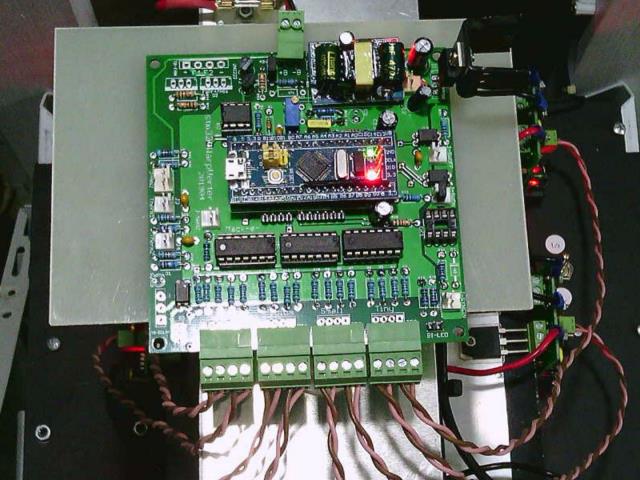 And with my own original board: 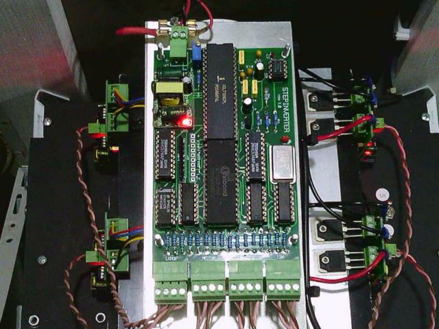 I have not shown any output waveform, it looks identical to my own output waveform which everyone is probably tired of seeing by now. Cheers, ĀTony. |
||||
LadyN Guru Joined: 26/01/2019 Location: United StatesPosts: 408 |
He he Tony! I am telling you, before you know it, you will stop worrying about crashing code too much and start loving the stm32 and ESP32! Order some stm32 and ESP32 today and start playing around! You will absolutely love it and I can't wait to see the magic you build out of them. The risk with that particular stm32 board is there's a tiny little 3v3 LDO at the back of it. That is the weakest point. It's not meant for continuous use. Not a concern if the 3v3 is fed externally, bypassing the LDO. |
||||
| Warpspeed Guru Joined: 09/08/2007 Location: AustraliaPosts: 4406 |
I have always worked as part of a team, and I left the bits and the bytes to the software magicians. I just busied myself with designing solid reliable hardware which in many ways can be more critical in a mass produced commercial product. But you are quite right. I must eventually start to lean a bit more about it. Cheers, ĀTony. |
||||
| The Back Shed's forum code is written, and hosted, in Australia. | © JAQ Software 2026 |
