|

|
Forum Index : Electronics : Homemade Transformer problems
| Author | Message | ||||
| BenandAmber Guru Joined: 16/02/2019 Location: United StatesPosts: 961 |
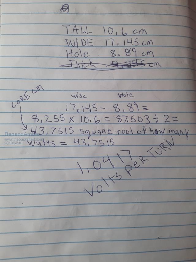
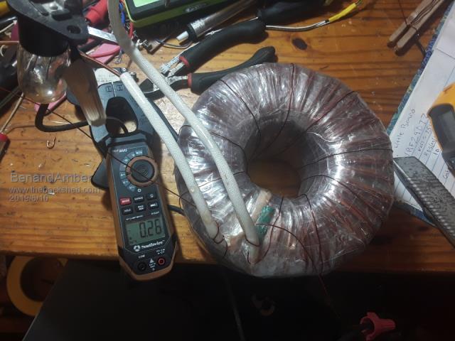
This Transformer is the one that I made out of several small ones I unwound all the small ones and rewound this bigger one on a sewer pipe as a form for the center Here is the chicken scratch on it  I fired it up with a light bulb no low side primary on it yet The clamp meter said 0.37 amps Me and another friend on here thought this was really high So I found a scrap piece of wire and wrapped nine more turns on it just to see what would happen Here are the results  Okay this looks a little better The problem is I thought I already overwound it I'm pretty sure the first layer was 86 second layer was 70 or somewhere real close to that Every time I've used this formula for calculating how many turns I add about another 10 turns and works out great Normally I would have put about 130 turns on this Transformer with this calculation I didn't want to unwind and spread the wire out evenly so I just kept winding until I filled up the second layer I need to get some of that good wisdom that comes from this form so I can wrap my head around this Thank you guys in advance for your help I'm so indecisive anymore that you guys just don't know how big of a help you truly are God bless all of you be warned i am good parrot but Dumber than a box of rocks |
||||
renewableMark Guru Joined: 09/12/2017 Location: AustraliaPosts: 1678 |
Ben, when I have wound toroids, I wound the secondary (240v output) with 2mm2 wire. To get the amp rating up 4 secondary winding's got used. And the output of each one got paralleled. Fortunately all 128 windings fitted on one layer, so it ended up with 4 neat layers of 4 secondary windings all exactly the same number of turns. Each secondary had exactly the same number of turns, (128 secondaries to suit 240v) That toroid ended up with 14 turns for the primary(48vdc) winding. That is the idea of doing the light bulb test for soft start and making sure the voltages across the loose ends are the same before you solder them together. This is the instructions from Oz I went by to wind my toroids. Can you clarify exactly what you have wound there? Cheers Caveman Mark Off grid eastern Melb |
||||
| Warpspeed Guru Joined: 09/08/2007 Location: AustraliaPosts: 4406 |
Hi Ben, Try plugging the numbers into a flux calculator like this one: https://www.daycounter.com/Calculators/Max-Flux-Density-Calculator.phtml Your numbers work out to 12,100 Gauss or 1.21 Teslas in metric. If I was doing this, I would design for 1.0 Tesla which would require 188 Turns. voltage 220v Frequency .00006 Mhz (60Hz) Turns 188 Area 43.75 cm sq Flux density 10,040 Gauss That will give a substantial drop to the idling power and any inrush surge. Cheers, Tony. |
||||
| BenandAmber Guru Joined: 16/02/2019 Location: United StatesPosts: 961 |
I wound 10 more turns to the 9 turns I wound previously and got it down to .21 so for 10 turns I got .04 more reduction Seems like diminishing returns to me I remember reading about this on one of your post- warpspeed thanks by the way for your advice warp speed your calculator said 0.03 I'm pretty sure I've done it wrong I don't understand it this inverter will be 110/120 volts only No split phase Renewable Mark thanks for the advice I wound the toroid until it got completely filled up this was my first layer I epoxy it and then wound two layers of Transformer tape then wound my second layer epoxy it and then wound 2 layers of Transformer tape I wound it like one single long winding of big wire Square wire not round I think it was a little over two mm by 2 mm So it should handle more amps than the core If I would have been winding multiple wires in hand I would have done it like you're saying I would make sure both the first layer And second layer was the exact same I think this is just the best this Transformer will do I don't guess it's too bad About 25 watts on Transformer alone I have a square Transformer that is about 3 to 4000 Watts it uses.07 amp idle current I am thinking about putting it in the inverter instead I was hoping to save it for my warp-speed inverter though I may be wrong but I think I'm getting to the same result that you guys would just doing it upside down and backwards What kind of idle current do you guys get out of your inverters be warned i am good parrot but Dumber than a box of rocks |
||||
renewableMark Guru Joined: 09/12/2017 Location: AustraliaPosts: 1678 |
I got worried and thought you did two separate windings. What cores did you use for this? Cheers Caveman Mark Off grid eastern Melb |
||||
| Warpspeed Guru Joined: 09/08/2007 Location: AustraliaPosts: 4406 |
Two separate windings might have been better. Lets see. Hole diameter 88.9mm, circumference about 279mm. In theory about 139 turns of 2mm wide wire should fit onto the first layer, and six less (133 turns) on a second layer, and 127 turns on a third layer. You will never get that, but lets assume three layers with about 110 turns on each layer should be a very easy fit. So we plug the numbers into the flux calculator. Volts 120 Frequency 0.00006Mhz Turns 110 Area 43.75cm Flux 9,360 Gauss (0.93 Teslas) 2mm x 2mm rectangular copper = 4mm sq about 16 amps per layer. Three layers 48 amps at 120v = 5.76 Kw. Three layers of 2mm wire might take up about 9mm, or reduce the hole size by 18mm leaving probably about a 70mm hole for the primary, which should be plenty. Cheers, Tony. |
||||
| BenandAmber Guru Joined: 16/02/2019 Location: United StatesPosts: 961 |
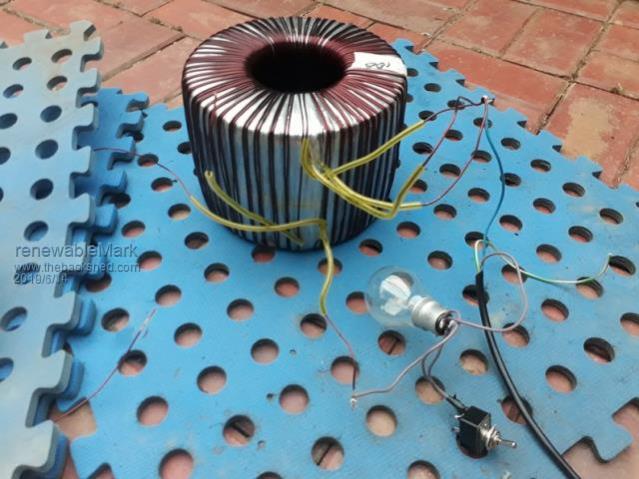
Me and a good friend on here has been talking back and forth We have decided to run with this homemade Transformer and see how it goes most likely it will have really high idle current It likely has a shorted turn I was very careful make sure this did not happen I re enameled The Wire And I also epoxied it When building this it seems like it should have used a lot more silicon Steel For the size of the toroid that it made It also took a lot more turns than I was expecting ( probably shorted) The wire was in horrible shape that's why I re-enamel it If I do find out that it has a shorted turn  I will probably rewind it with new wire There will be a teardown if idle current is unacceptable be warned i am good parrot but Dumber than a box of rocks |
||||
renewableMark Guru Joined: 09/12/2017 Location: AustraliaPosts: 1678 |
Looking back through my notes my toroid did 16w idle. It may have something to do with the fact you hand wound the silicon steel strip, it wouldn't have been as tight as a machine made one. Cheers Caveman Mark Off grid eastern Melb |
||||
| Warpspeed Guru Joined: 09/08/2007 Location: AustraliaPosts: 4406 |
Its easy enough to measure core loss with just a bare steel toroid core. Wrap around some test turns, say for example ten turns of plastic insulated wire. Connect that up to a variac and slowly increase the voltage while measuring both the voltage and the current. You will find that the drive power rises very steeply as the volts per turn increases. Decide what idling power would be a reasonable compromise, and use that volts per turn to design all your windings. Very low idling power requires a LOT of turns which may not be able to fit on the core with wire thick enough not to overheat at full power. Using very thick wire means less turns are possible producing a higher idling power. But doing the idling power test first will give some useful figures to work from, and a pretty good idea of how its all going to end up. My own 5Kw transformer has 20 Va of measured idling power. I did not test the bare core, but it has 90 turns for 225v about 2.5 volts per turn. If I had used a ten turn test winding on that core, I should have measured about 800mA at 25 applied volts. That is the same 20Va as measured with 2.5 volts per turn. So if I had used that 2.5v per turn as my design goal it would have given the right answer for 90 turns = 225v producing the expected 20 Va of idling power. Cheers, Tony. |
||||
| BenandAmber Guru Joined: 16/02/2019 Location: United StatesPosts: 961 |
I'm not doing something right or my multimeter don't work right because I checked the APC 3000va Square Transformers I have they had .44 idle current I have four of them all together but it takes two of them to make that 3000 VA tested only one of them at a time they all gave the same I would use a set of these or maybe the big square one I have if I had to but I'm trying to save them for the warp speed inverter I will keep everyone posted The Wire was really hard to wrap it's very thick wire I could have shorted out a turn I understand why all you guys use multiple smaller wires If it don't work out I will get to the bottom of it if possible so everyone will know where I messed up Thanks for all your thoughts and wisdom be warned i am good parrot but Dumber than a box of rocks |
||||
renewableMark Guru Joined: 09/12/2017 Location: AustraliaPosts: 1678 |
 Are you shorting out the light bulb after the soft start? You should have a switch fitted across the bulb terminals. Have it open to do the soft start, then close/short the switch to eliminate that from the circuit. BE CAREFUL DOING THIS, VERY EASY TO ZAP YOURSELF. Cheers Caveman Mark Off grid eastern Melb |
||||
| BenandAmber Guru Joined: 16/02/2019 Location: United StatesPosts: 961 |
Yep with a lightbulb and a switch Now that I measured those Square Transformers I'm a lot more optimistic in the toroid being just fine I wound the transformer for my soldering station when it blew up I've winded countless Transformers 4 battery chargers Never really wound real big transformers until inverters though They've always worked out even though I really didn't know what I was doing It'll be a while before we see how it turns out Slow boat from China you know how that goes I did get all the parts ordered for the Nanos I'm pretty sure it took me a lot longer to order the parts and what it's going to take me to solder in I ended up getting capacitor kits And resistor kits it made it easier Also ordered one of Mads 8 thousand watt board be warned i am good parrot but Dumber than a box of rocks |
||||
| oreo Senior Member Joined: 11/12/2020 Location: CanadaPosts: 117 |
Sorry for bumping this old thread, but I have a couple questions for the OP/anyone with experience. 1. Just wondering if rewinding the core using smaller transformer cores worked out for you? Did it have the idling current you expected? 2. How did you hold the core strip from each core to each other? (I am seeing that manufacturers spot weld them, however that is not really DIY) 3. Any other suggestions on doing this? The reason I ask, is I have a fairly large cache of 3.5kg cores, which I was thinking of rewinding into 1 core, if it is feasible. thanks! Greg |
||||
| InPhase Senior Member Joined: 15/12/2020 Location: United StatesPosts: 178 |
What would testing the high voltage winding of the transformer on mains power tell us about the idle current of the low voltage primary? It doesn't idle from mains. It idles from battery power. Seems like you would want to measure the low voltage idle and get that in tune instead. After all, the high voltage winding would have no load at idle and would be an open circuit. |
||||
| Warpspeed Guru Joined: 09/08/2007 Location: AustraliaPosts: 4406 |
It does not matter which winding we use to test the transformer idle power with. Its the core that consumes the idling power. You could even wrap a few extra new turns around the outside of all the existing windings and test with that. The results will always be identical idling power in each case. It could be 230v and 100mA = 23Va Or 2.3v at 10amps using only two turns, also = 23Va Cheers, Tony. |
||||
| rogerdw Guru Joined: 22/10/2019 Location: AustraliaPosts: 935 |
Thanks for asking the questions Greg as they are ones I was going to ask shortly myself. In fact spent an hour or more this morning looking at the subject. 3. Initially I thought I could literally superglue one end to the core and immediately clamp it ... then wait till it set, then carefully wind until I had it holding itself under tension and finish it off ... then superglue and tape until set. Then add the mylar which would bind and keep it all together. If you watch some of the youtube videos on rewinding them, you see the ends of the cores are quite loose and at most are simply taped together. In fact one core I rewound for my Warpinverter was loose and could easily have become a slinky if I'd been careless. Since then I thought, I've always wanted a spot welder, so why not cobble one together and do it properly. Spotweld the start and the finish. Haven't completed it yet, but am half way there. Then of course the question of annealing comes up ... Needs roughly 800 degrees Centigrade (not Farenheit) ... and in a Nitrogen rich environment ... held for a couple hours ... and then ramped down over about 6 hours. Then it needs to be demagnetised!!! These are some of the things I've read ... but there are so many variables ... and not knowing the grade of the initial steel makes it well and truly a guessing game. In a lot of the articles I did read, they often mentioned cores for current transformers and several other specialist uses ... and I did wonder just how fussy a good old power tranformer would be ... ... and in one article they did actually add the disclaimer that a lot of the points they had just made weren't really all that important for power transformers. So I am interested to hear Tony's take on all that ... and anyone else who may have some expert advice to give. Cheers, Roger |
||||
| Warpspeed Guru Joined: 09/08/2007 Location: AustraliaPosts: 4406 |
As we already know, losses are measured in watts per Lb of core material at a given flux density. Idling watts increase proportional to increasing core volume (size). Idling watts increase at an exponentially ever increasing rate with increasing flux density. Its a very steeply rising curve, rising to infinity at full magnetic saturation. If we want to get low idling power, we design for a low flux density, and just accept that its going to require a lot more turns for any given voltage. The problem with that is more turns requires thinner wire which gets hotter and limits our power rating for a given core size. So basically a grid powered commercial transformer will run at a high flux density and have a high power rating and may have appallingly high no load losses. It will use less steel and less copper and be smaller and cheaper. In many applications it NEVER runs at zero load anyway, but powers something continuously whenever its switched on. A 2Kw transformer that has 100 watts of idling power loss is no problem in many applications. A really good inverter transformer is very different. It will be designed for a much lower flux density, use a larger core, have more turns, use a lot more copper, and be more expensive, but have very low idling power. Maybe 20 watts or less for a 2Kw transformer. The quality of the steel comes into this as well. The really good stuff is naturally more expensive. The right steel/silicon alloys, proper heat treatment, and thin laminations all help to create a higher inductance per turn, lower eddy current loss, and higher impedance, all of which reduces the idling current. Steel quality is a bit of a lucky dip with secondhand materials, especially from China. Cheers, Tony. |
||||
| Warpspeed Guru Joined: 09/08/2007 Location: AustraliaPosts: 4406 |
There is no simple straightforward list of steps for designing a transformer. Basically you start out by guessing the size of the core for the required power. From the core cross section, calculate the turns required at your target flux density, which for toroids might be 1 Tesla or 10,000 Gauss in imperial. Work out the required wire sizes using a recommended current density of 4 amps per mm square. Se if its going to fit onto the core. It probably either will not fit, or there will be excess room for the windings. Rinse and repeat with a different sized core, until all the numbers look reasonable. If its a brand new core, there will be data for watts per pound at your operating frequency and flux density. If its some recycled junk, a test winding with say ten turns and a variac, and its possible to measure the ac volts and ac amps and come up with an idling power number. Wind up the wick until you reach some reasonable idling power. That will give you the volts per turn directly from your test winding. If you use that same volts per turn to design your transformer, the final idling power should be the same once its rewound. Cheers, Tony. |
||||
| The Back Shed's forum code is written, and hosted, in Australia. | © JAQ Software 2025 |