| Author |
Message |
FandPwithPVC
Regular Member

Joined: 09/09/2006
Location: Posts: 64 |
| Posted: 07:47am 13 Jul 2008 |
 Copy link to clipboard Copy link to clipboard |
 Print this post |
|
Hi All
For this to work you need to find/scrouge two or more non polorized capaciters say of 100 uF.
They need to be at least 100 VDC and of large dimension. They are fairly common particularly in power supplies.
To make them work as non polorized ac types they need to be connected negative to negative or positive to positive. They then become AC. It would be hard to measure there new combined output which will be 100 uF . I am unsure about there new voltage as I missed my technical advisers answer.
The above is an alternative way of using caps.
All For Now Regards Dennis L |
| |
herbnz

Senior Member

Joined: 18/02/2007
Location: New ZealandPosts: 258 |
| Posted: 08:55pm 13 Jul 2008 |
Copy link to clipboard |
Print this post |
|
herbEdited by herbnz 2008-07-18 |
| |
Gill

Senior Member
Joined: 11/11/2006
Location: AustraliaPosts: 669 |
| Posted: 02:24am 14 Jul 2008 |
Copy link to clipboard |
Print this post |
|
At first I thought you were describing how to parallel two caps but with one in reverse polarisation, but then you say neg to neg and pos to pos. So I too am confused. Perhaps a sketch of the arrangement? 
was working fine... til the smoke got out.
Cheers Gill _Cairns, FNQ |
| |
oztules

Guru

Joined: 26/07/2007
Location: AustraliaPosts: 1686 |
| Posted: 08:22am 15 Jul 2008 |
Copy link to clipboard |
Print this post |
|
Putting two electro's back to back to get a non-polarised capacitor is quite do-able...... however.....
I haven't had long term success with this arrangement, even when I have only wanted a few uf. Others have claimed a degree of success that I have not experienced.
It should work in practice, as well as theory.... but keep wearing eye protection unless the brute physical size of the caps can keep them cool enough to not go boom.
I particularly dislike that paper fluffy sticky stuff that sticks to your glasses after being caught too close to the "event horizon"
The capacitors in series you describe are useful for driving a heating load without switching in and out. At low frequencies the capacitors pass low current when compared to direct connect, and so avoid stalled blades that don't start well.
This sort of acts like having a cut-in without batteries, which allows the revs to build up before milking the current into the load.
I am wondering if the increase in performance at Pedlers Creek under this regime is more due to the prop being allowed to run faster, and so develop more power for the same winds. Similar to adding line resistance to match the load better. ie ExE/R with R getting smaller while E gets bigger.
In this case, the "resistor" varies with the frequency and becomes less of a resistance as the power moves up... unlike that of the resistor, which sheds more and more power as the current goes up. ExE/R ....resistance stays essentially the same but voltage only goes up.
May solve some peoples mismatches where the alt is a bit stiff at low range, and you would normally add resistance to get away from stall.
I would steer away from back to back polarised electro's based on my previous experiences, .... but others have had success. I would continue to use run caps for this application.
It is just another in a long line of things that can improve outputs by matching the load a little better (if it is poorly matched in the first place that is.
.........oztules
Village idiot...or... just another hack out of his depth |
| |
oztules
Guru
Joined: 26/07/2007
Location: AustraliaPosts: 1686 |
| Posted: 08:53am 15 Jul 2008 |
Copy link to clipboard |
Print this post |
|
Dennis,
Making non-polarised capacitors from two polarised caps does the following:
1. The voltage remains the same as the original single capacitor. The (each) capacitor cycles between potential and zero for each normal view, not between zero and half potential (like in a H bridge configuration), or half voltage plus and half voltage minus.
2. The capacitance is halved.
3. Diodes will make no difference at all and are a waste of component. The asymmetric leakage effectively does the same as a diode would do.
4. do not use equalising resistors ( if you are tempted to). If you do , then you need the diodes, and it will do more harm than good. Best without.
5. Essentially manufactured non-polarised caps are two normal polarised caps with the plus terminals to the outside and the cans negatives connected inside the cap.
So what you are doing it is not strange, or weird, this is how they are kind of made anyway (without diodes or equalising resistors though). BUT remember the start caps from induction motors are usually big non-polarised ones, and are for intermittent use only.
Like I said, I have not had good results for more than intermittent use. If you size them big enough you may sneak in with better success than me.
.......oztulesEdited by oztules 2008-07-16
Village idiot...or... just another hack out of his depth |
| |
FandPwithPVC
Regular Member
Joined: 09/09/2006
Location: Posts: 64 |
| Posted: 10:24am 15 Jul 2008 |
Copy link to clipboard |
Print this post |
|
Hi Oztules You have provided 2 replies on this subject. One is complicated and the other is simple. We much prefer the simple one. Anyhow in regard the above it was NEVER our intention to use equaliZing resistors or diodes . This was suggested by another person who is probably not doing what we are doing anyhow, We will conduct ongoing experiments with small and large non polorized capaciters. There will be some explosions and we are both prepared for and expecting this. ( Looking forward to it )
It is said you can not make fire without smoke.
Regards Dennis L |
| |
oztules
Guru
Joined: 26/07/2007
Location: AustraliaPosts: 1686 |
| Posted: 11:18am 15 Jul 2008 |
Copy link to clipboard |
Print this post |
|
Hi Dennis,
A few explosions here and there that you can walk away from helps keep the interest up. 
From Memory, Zubbly ran very large caps in this configuration, and whilst they heated up considerably, they held together. He was passing a few KW I think, but it seems that size is important.
Best of luck with this, and hopefully we will all learn something from your tireless pursuit. 
The resistor / diode thing seems always to crop up when this use of caps is discussed. I figured we may as well put it to bed early. I know you weren't advocating this.
........oztules
Village idiot...or... just another hack out of his depth |
| |
Bryan1

Guru
Joined: 22/02/2006
Location: AustraliaPosts: 1210 |
| Posted: 04:46am 20 Jul 2008 |
Copy link to clipboard |
Print this post |
|
Well Guy's I just went and unsoldered about 36 400 volt caps. All the caps are off brandnew boards I got from work for nothing and I have 3 different uf ratings 330, 470 and 680 uf. I have 12 of each and 10 of the 680uf ones so now the fun will begin.
Cheers BryanEdited by Bryan1 2008-07-21 |
| |
BUGS

Newbie

Joined: 12/04/2007
Location: AustraliaPosts: 21 |
| Posted: 09:53am 24 Jul 2008 |
Copy link to clipboard |
Print this post |
|
I found this,may help some one. Regards Ivan
BUGS |
| |
Bryan1
Guru
Joined: 22/02/2006
Location: AustraliaPosts: 1210 |
| Posted: 09:33am 29 Jul 2008 |
Copy link to clipboard |
Print this post |
|
Well Guys,
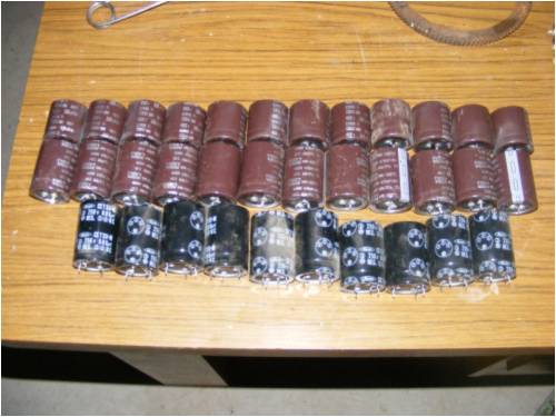
I was up in my shed tonight working on my my cnc project when I heard the genny take off So I went and turned on the fluke on scope view and the cheap dmm on 10 amp and instantly saw 8 amps on the dmm. I did watch it for about 10 minutes and it looks like 6 of those caps in the picture above, the middle ones 400 volt 470uf put back to back they measured between 216-219uf on the fluke are doing great. I still have the 100S wired in delta and where the genny had to be going like the clapper to make 5 amps with the caps it was doing it easy We're in for storms all week so hopefully tomorrow night I'll get some pic's of the waveform on the fluke and the current on a cheap 30 amp current guage from smithy dicks.
Cheers Bryan |
| |
oztules
Guru
Joined: 26/07/2007
Location: AustraliaPosts: 1686 |
| Posted: 10:12am 29 Jul 2008 |
Copy link to clipboard |
Print this post |
|
Sounds like a happy Bryan.
What configuration are you using the caps in (parallel or series)
How was the temperature of the caps doing.
Hopefully the storms will come south some and dump more rain here as well.
.........oztules
Village idiot...or... just another hack out of his depth |
| |
Bryan1
Guru
Joined: 22/02/2006
Location: AustraliaPosts: 1210 |
| Posted: 07:56am 30 Jul 2008 |
Copy link to clipboard |
Print this post |
|
G'day Oz,
I simply soldered the 2 negative leads together with some 2.5mm wire and soldered some longer wire on each end of the postive lead to connect them to each phase. All up I used 6 of them, 2 for each phase.
Now here's a good question for ya mate Lets say I put 50 or so of those caps in parrallel after the recifier along with a blocking diode from the batterybank. I'm thinking when the cutin starts the caps would hold the voltage then when the genny drops below cutin the caps would discharge current into the batteries. Do you reckon this would be feasable or a waste of time???
Cheers Bryan |
| |
oztules
Guru
Joined: 26/07/2007
Location: AustraliaPosts: 1686 |
| Posted: 09:05am 30 Jul 2008 |
Copy link to clipboard |
Print this post |
|
I think the only noticeable difference would be to delay startup. The caps would start charging from just over zero volts, and so load the mill just when you don't want it. When the mill finally overcomes the charge load of the caps, they will remain mostly out of circuit until you fall below startup, they would then discharge a tiny bit trying to hold just above startup volts.
As the voltage drops below start up, the caps would maintain their charge until cut in was achieved again. They would then follow the battery volts until below start again...
The caps can no more charge the batteries below cutin volts than the Mill can.
I can see no joy from this arrangement. 
If you want to charge below cutin rpm (if there is any worthwhile energy there in the first place worth capturing) then those circuits of Bugs above will help some. But if sized too big may curb cutin too.
.........oztules
Village idiot...or... just another hack out of his depth |
| |
Bryan1
Guru
Joined: 22/02/2006
Location: AustraliaPosts: 1210 |
| Posted: 09:51am 30 Jul 2008 |
Copy link to clipboard |
Print this post |
|
Hi Oz,
Thank you for the explanation, now I suppose with all these caps I have if people want any I can always post a few so others can try themselves. If you like Oz I can put a bundle of them together and post them over. now I did say ages ago I was going to give you a box of goodies so now theirs somemore stuff to throw in 
|
| |
oztules
Guru
Joined: 26/07/2007
Location: AustraliaPosts: 1686 |
| Posted: 10:40am 30 Jul 2008 |
Copy link to clipboard |
Print this post |
|
Thanks for the offer Brian. I have plenty of this kind of Electro cap. (old PSU's are good for this and have good temp and ripple figures.)
I'm guessing your using delta. How is the temperature of the caps?
I have just been reading about your recent blade ordeal, and have just decided that tomorrow I will carve (or hack up and make firewood) some 4 meter blades with a chainsaw. If successful I will do a thing on it. I think it will be easy ....... but I've said that before too....
Dinges will be mortified...... Flinders Island chainsaw massacre.
..............oztules Edited by oztules 2008-07-31
Village idiot...or... just another hack out of his depth |
| |
