
|
|
Forum Index : Electronics : the ubiquitous 555
| Page 1 of 2 |
|||||
| Author | Message | ||||
mackoffgrid Guru Joined: 13/03/2017 Location: AustraliaPosts: 460 |
Nostalgia, the Moon Landing thread, and Tony's Simplified Solar Hot Water thread ; Natasha's statement had me thinking how ubiquitous the humble 555 is. My very first project, many decades ago, was a 555 two tone doorbell. Since I've used them for all sorts of things including astables, bistables, flip flops, modulators, demodulators, and the list goes on. Here's a list  50 555 circuits 50 555 circuits I can't say my 555 circuits are particularly clever - barely remember what I've done  but it'd be interesting and possibly challenging to see some clever 555 circuits before tiny micros totally replace the humble 555. but it'd be interesting and possibly challenging to see some clever 555 circuits before tiny micros totally replace the humble 555.Cheers Andrew |
||||
| Poppy Guru Joined: 25/07/2019 Location: GermanyPosts: 486 |
Hi Andrew, I agree, the 555 is such a little nice thing and for starting hobby electronics and somehow later it still is the  best IC to play around with! best IC to play around with!Some more reading: https://archive.org/details/Signetics555556Timers https://archive.org/details/555TimerAndItsApplicationsSharma https://archive.org/details/electronics_-_Forrest_Mims-engineers_mini-notebook_555_timer_circuits_radio_sha https://archive.org/details/TimerOpAmpOptoelectronicCircuitsProjects Andre ... such a GURU? | ||||
| westie42 Newbie Joined: 25/09/2017 Location: New ZealandPosts: 3 |
evening andrew i think the 555 was the first ic i ever played with and i still keep a good supply of them in the shed , as with anything electronic theres not one " correct " way of doing things . i often find myself coming up with some over engineered way of building a circuit only to relies a 555 will do it my last project was two way garden light switching on two wires i made up a nice pcb with power supply / relay and 555 working as a 2 second -filp flop timer with n/o buttons at the shed and house end if you look past the timing functions theres so much more to these chips the the opamps and flip flops in the chip can be used for all sorts i saw a class D (switching) amplifier built with one i dont many chips can boast being in production for so long 741 op amp ? mike |
||||
| Warpspeed Guru Joined: 09/08/2007 Location: AustraliaPosts: 4406 |
They are certainly a very versatile chip. I have always kept a few here for as long as I can remember, and still occasionally find them very useful. Recently made another batch of battery cell balancing and monitoring boards, this has been an ongoing project over the last couple of years, now into the fifth iteration. And yup, each of the thirty boards has a CMOS 7555 on it. Cheers, ĀTony. |
||||
| westie42 Newbie Joined: 25/09/2017 Location: New ZealandPosts: 3 |
hi tony what type of cells ? im looking to do a small board to make use of my ever growing pile of 18650 cells thinking of 2 cells using a pair of LM317s , one as a voltage reg and one following as a current limit to charge then an mc34063 to step up / down ( as required ) to give 3.3/5/9/12v output make it a module that can be integrated into various projects - any thoughts would be appreciated thanks mike |
||||
| mackoffgrid Guru Joined: 13/03/2017 Location: AustraliaPosts: 460 |
Hi guys Tony, I'm glad to see a 7555 in another circuit I promise I didn't set this up, but as an example I'm planning my new cell balancing and monitoring system. It doesn't have a 555. I'm planning on using a little, very low power, 8 pin microprocessor across each battery, connected by an isolated serial buss. I am keen to see how a 7555 is used in a cell balancing - monitoring circuit. cheers Andrew |
||||
| Davo99 Guru Joined: 03/06/2019 Location: AustraliaPosts: 1585 |
I ordered some a couple of weeks ago to build one of Tonys Circuits. I couldn't believe the price, $1.20 for 20 of them delivered! I seem to remember paying 5 bucks for them when I was a kid to build different things. Also remember cooking a few of them too before I learned grandads old 120W soldering iron he used on roof guttering had a bit too much steam to it for electronics combined with non soldering skills at the time.  |
||||
| Warpspeed Guru Joined: 09/08/2007 Location: AustraliaPosts: 4406 |
Ah..... This has been a very long ongoing saga, but here is the short version. I have thirty series connected Winston 50Ah lithium cells that I wish to both monitor individually and balance individually. To get a consistently accurate comparison of individual cell voltages, a single floating voltmeter appears to be the only reliable way to do this. That involves switching each cell sequentially onto a common 3v monitoring bus, to which a floating voltmeter is attached. The individual cells are stacked physically 6x5 which fits very nicely into a standard filing cabinet drawer. To minimise the cell selection wiring, the individual cell monitoring boards are multiplexed into six columns and five rows. That only requires eleven wires to select any one of thirty cells for voltage measurement. Each cell monitoring board originally had the usual cell balancing discharge load resistor and a voltage comparator (TL431) and a potentiometer for very fine calibration adjustment. It worked but I could never get all thirty cells to balance within the very few millivolts I was striving for, mainly because the thirty discharge loads could never all be set to work the same exact precise voltages. So I needed a way to turn each of these discharge loads on and off individually by software based on the voltage measured by the common voltmeter. I really did not want to add more wiring to the cell monitoring boards, so I worked out a way to do it through the original multiplexer wiring without adding any more hardware to what was already there, except for the revised cell monitoring boards themselves. The way the system works, a particular cell is selected for voltage measurement by sourcing +12v to a row, and sinking current to a particular column. This activated a couple of opto isolated analog switches to connect the selected cell to the common measurement bus.  A third opto isolator sends a logic signal to clock a D type flip flop. Whenever a particular cell is selected, its flip flop gets clocked on the rising edge. The data input to the flip flop comes from a long time constant RC integrator fed off the same opto isolator. The result of this is, that every time a cell is accessed the flip flop turns off and would normally stay turned off because the D input has been low for a very long time while the other 29 cells are being measured. While the selected cell is having its voltage measured, the integrator at the D input to the flip flop slowly rises logic high. If the multiplexing to the cell is quickly removed and replaced, the flip flop goes logic high, and stays high. So I can quickly glitch the multiplexing on the trailing edge which turns on the flip flop. No glitch, the flip flop stays off. By that means I can control each cell discharging load with software not requiring any extra wiring or hardware at the BMS end of the system. To prevent the discharge load from winking on and off every time a cell is being measured, I used another long time constant and a 7555 timer to control the discharge load. This switches very cleanly and at an accurate voltage theshold and provides a very nice 3v logic signal for the FET which switches the discharge load resistor. Its quite a complex circuit for what it does, but it draws very little power and required no extra wiring from what was previously there. I can now switch my balancing loads on and off individually with one bit resolution from the measurement voltmeter, knowing every cell will have exactly the same voltage balancing thresholds set by software. VERY happy with the improved cell balance this system produced. Cheers, ĀTony. |
||||
| mackoffgrid Guru Joined: 13/03/2017 Location: AustraliaPosts: 460 |
Very nice. I see the appeal of using just one volt meter. What sort of meter are you using? What is the scan rate? Cheers Andrew |
||||
| Warpspeed Guru Joined: 09/08/2007 Location: AustraliaPosts: 4406 |
Its just an ordinary microcontroller eight bit analog to digital converter. But the nice thing about it is that it has independent high and low reference voltage inputs. Fed with a 3.10v low reference voltage, and a 3.50v high reference voltage, I get 256 bits of resolution between 3.1v and 3.5v. That works out to about 1.6mV per bit. The microcontroller is ground referenced, but I use a "flying capacitor" galvanic voltage isolator between the cell, and the analog to digital converter. Cheers, ĀTony. |
||||
| Warpspeed Guru Joined: 09/08/2007 Location: AustraliaPosts: 4406 |
It scans through thirty cells in about twenty seconds. Its slow for several reasons. The opto data switches are slow, about one millisecond to turn on and off completely. I measure the voltage of each cell for 20mS taking 256 voltage readings over that period, that are then averaged. That gives a very clean accurate no jumping around voltage reading every time, in the presence of considerable heavy 100Hz ripple current from the inverter. There have been a great many problems to overcome getting all this working to my satisfaction, but its been a really interesting learning process. Cheers, ĀTony. |
||||
| mackoffgrid Guru Joined: 13/03/2017 Location: AustraliaPosts: 460 |
Twenty second scan rate, no problems, my OCD gene would have tweaked and had me do it at 1 second per cell. I've never used a flying capacitor circuit, how did you go with leakage etc? Cheers Andrew |
||||
| Warpspeed Guru Joined: 09/08/2007 Location: AustraliaPosts: 4406 |
That has been another long story. For cell selection onto the common bus I used slow switches with a fairly low on resistance (2 x 8 ohms) and a reasonably high current rating (350mA) for robustness. The flying capacitor switches need to be much faster, and are not subject to the same massive fault currents if the software crashes and tries to connect multiple cells simultaneously onto the common monitoring bus. The trick is to discover an optimum switching frequency, dead time, and suitable capacitor value for highest dc accuracy. Its not really possible to design this, it really works best with some practical testing. Just measure the cell voltage right at the cell, and again at the input to the A/D converter input. Should be possible to stay within 100uV over about a 10:1 switching frequency range, then it quickly degenerates to Hell at the extremes. All this testing is done initially without any very large common mode voltage to get clean switching from rather slow switches that have a significant on resistance. A completely different problem is dc leakage from a high common mode dc voltage, especially as the A/D input is a very high impedance. Some testing showed that I had just over 5mV of leakage for each 100v of common mode voltage. It was quite linear too. +10mV error at +200v and -15mV error at -300v and it did not change with temperature or mixing devices within a batch of ten that I had. So I simply added some straight line correction of -5mV per 100v of common mode, with a 10 meg resistor and 560 ohm resistor. It now has less than 1mV measurement error between the lowest cell at 0v and the highest cell in the string up at +100v. Cheers, ĀTony. |
||||
| Warpspeed Guru Joined: 09/08/2007 Location: AustraliaPosts: 4406 |
 Cheers, ĀTony. |
||||
| mackoffgrid Guru Joined: 13/03/2017 Location: AustraliaPosts: 460 |
Tony, I'm thinking of trying the flying capacitor idea, but only in a small 7 cell array. 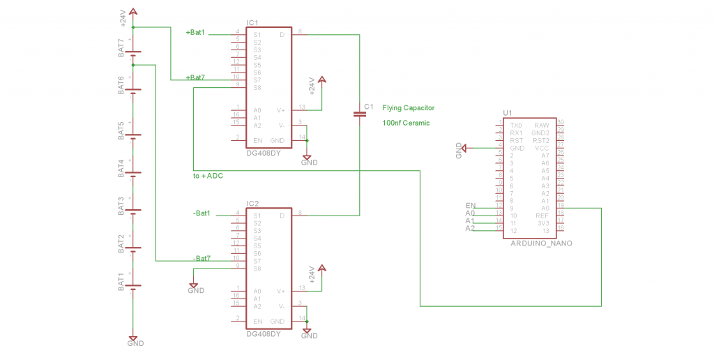 I don't need opto isolation and the DG408s will handle over 30V supply. I can use Enable of the DG408s as a dead time and switch in up to 7 cells. The DG408 does have an impedance of ~100R. I can't quite read all of your schematic but my in-complete schematic is close in principle? As there is heaps of time available to scan the batteries, inserting a 10k resistor from the + and - legs of the Flying cap wouldn't hurt? Cheers Andrew |
||||
| Warpspeed Guru Joined: 09/08/2007 Location: AustraliaPosts: 4406 |
Yes, that looks fine in principle. Just select the required cell by enabling the appropriate input, wait for the flying capacitor to fully charge. Maybe at least five time constants. (20us ?) Then connect the flying capacitor to the Nano, allowing sufficient dead time. And then read the voltage with the a/d converter. Now you may need to fiddle with this a bit to get absolute optimum performance. Try different values of flying capacitor, if its too big it will be slow to charge, if its too small it may lose some charge through leakage and the switching process. You may gain some accuracy and stability by fitting a second capacitor between the Nano a/d input and ground. It will then take several flying capacitor cycles to get that a/d input capacitor to charge up to the exact precise cell voltage, but there is plenty of time to do that. You can check with a multimeter. Measure the cell direct, then measure the voltage at the Nano, they should be identical. If its out by a millivolt or two, you can try a few things to get it right. If the inverter is working really hard, there will likely be some significant 100Hz ripple voltage on the battery. Another thing you can play with is averaging multiple a/d readings over a ten or twenty millisecond period. I take 256 readings over 20mS, add those together to get a sixteen bit result. The highest eight bits will be noise free and immune to 100Hz inverter ripple voltage, no one bit measurement ambiguity either. With a bit of experimentation and stuffing around, its possible to get completely noise free cell voltage readings to one bit (millivolt) resolution that does not jump around from reading to reading. Cheers, ĀTony. |
||||
| mackoffgrid Guru Joined: 13/03/2017 Location: AustraliaPosts: 460 |
Thanks Tony As I said I haven't used a flying capacitor before and I just wanted to make sure I hadn't missed something. All good ideas  The ADC capacitor is worth a try and the 256 sampling over the 20ms cycle is a good idea as well. The ADC capacitor is worth a try and the 256 sampling over the 20ms cycle is a good idea as well.I hope to test this idea soon. I'll let you know how I go. Cheers Andrew |
||||
| Warpspeed Guru Joined: 09/08/2007 Location: AustraliaPosts: 4406 |
That DG408 looks like the ideal device as it can work up to 44v single supply, and the control inputs are logic level shifted to suit, and are also compatible with 3v logic. Nice find Andrew. Edited 2019-09-07 07:27 by Warpspeed Cheers, ĀTony. |
||||
| mackoffgrid Guru Joined: 13/03/2017 Location: AustraliaPosts: 460 |
Yes, a useful part. Connect the -V to GND and she's good. I "Hope" to have an interesting project with this but I have to make some tests first. Cheers Andrew |
||||
| Warpspeed Guru Joined: 09/08/2007 Location: AustraliaPosts: 4406 |
I experimented with different flying capacitor values, and different switching frequencies. Tried all different combinations. I found something that would work over about a 20:1 switching frequency range with negligible error, but beyond that it started to lose accuracy at either very fast or very slow rates. Twenty to one is not bad, so it ended up in the middle of that. Its completely noise free and very consistent. Very happy with the outcome. Cheers, ĀTony. |
||||
| Page 1 of 2 |
|||||
| The Back Shed's forum code is written, and hosted, in Australia. | © JAQ Software 2026 |
