| |
Page 1 of 2   |
| Author |
Message |
philb

Regular Member

Joined: 05/07/2008
Location: United StatesPosts: 96 |
| Posted: 03:20pm 16 Jul 2008 |
 Copy link to clipboard Copy link to clipboard |
 Print this post |
|
Is there a relatively cheap devise or plans available that can take power in the range of 250 VDC to 500VDC from a wind generator and convert it directly into 120 VAC or 240VAC? I am thinking a switch mode power supply may work. The BIG drawback: I need it for a 5000 watt generator.  Power grid connection would be nice, but not mandatory. Power grid connection would be nice, but not mandatory.
Some of these same grid tied units are available through SW windpower and Bergey wind. In both cases, they are not sold seperately from their generators.
Any thoughts?
philb |
| |
Haxby

Guru

Joined: 07/07/2008
Location: AustraliaPosts: 423 |
| Posted: 11:29pm 16 Jul 2008 |
Copy link to clipboard |
Print this post |
|
If the requirement was between 100 and 350 volts then 10 computer power supplies could be used to regulate the voltage then an off the shelf inverter could be used to provide the power.
What exact measurements of voltage do you have under a 5KW load?
if you have 350 or less volts at 5kw load then it will work, you need an add on circuit to ensure the mill is loaded and never goes above 380 volts.
If you are serious about the project then let me know as I have something suitable.
Edited by Haxby 2008-07-18 |
| |
philb
Regular Member
Joined: 05/07/2008
Location: United StatesPosts: 96 |
| Posted: 12:55am 17 Jul 2008 |
Copy link to clipboard |
Print this post |
|
Haxby,
Thanks for your reply. I am very serious about this project. My wind generator that I have in mind normally goes to 3000 watts. Open circuit voltage puts the unit at greater than 120 VAC on each leg. I think I need a little room as I have not measured it voltage in high wind. 60 MPH are not uncommon here on a monthly basis.This is the generator. http://www.fieldlines.com/story/2007/6/2/17930/85949.
I plan to make a second one that is going to be a 16 foot prop. BTW, Oztules, Dinges and SparWeb have me thinking about an electric motor conversion after that. It make more sense.
I want to combine the VDC on multiple generators for the trip to my house/greenhouse/EV area. So the voltages must remain relatively high because of the distance transported is over 1500 feet.The first one might produce 120 VAC in 10 MPH and furl at 20 MPH. The second may cutin at 15 mph and furl at 30 mph. This is in the thinking area (options for now). I need to see what units/plans are available.
I am not a pic programmer, but I can probably do it if that's the only way to accomplish the goal without taking drastic steps. The voltage can be limited by using zeners. That is being used on several commercial units. There are plenty in stock at parts houses and cheap!
What do you have in mind on power supplies? 
philb |
| |
Haxby
Guru
Joined: 07/07/2008
Location: AustraliaPosts: 423 |
| Posted: 06:15am 17 Jul 2008 |
Copy link to clipboard |
Print this post |
|
Computer switch mode power supplies take a 90V AC to 250V AC input and regulate to 12V DC.
The first thing they do is rectify the AC into DC. But you can run them from DC directly from the get go.
Newer power supplies have exceptional current handling ability on the 12V rail. This can be around 40A.
So a 5KW supply would mean 10 computer power supplies hooked up to the mill. Then use the regulated power for whatever you like.
But you will have to graph power output vs Voltage before you can find out if a computer power supply will suit your needs. If there is not enough voltage at lower powers, you will have to think of something else. But there are options. Such as switching from series/parallel, delta, star etc.
The other part of it is the mppt. But that can be tackled at the battery end.
If the battery end knows how much power is being generated, it can PWM the batteries accordingly.
|
| |
philb
Regular Member
Joined: 05/07/2008
Location: United StatesPosts: 96 |
| Posted: 03:04pm 17 Jul 2008 |
Copy link to clipboard |
Print this post |
|
"Computer switch mode power supplies take a 90V AC to 250V AC input and regulate to 12V DC."
I want to regulate the output to 120 VAC or 240 VAC. Maybe it is possible to modify PSU's to produce higher voltages. 
Thanks for your reply.
philb |
| |
oztules

Guru
Joined: 26/07/2007
Location: AustraliaPosts: 1686 |
| Posted: 11:10pm 17 Jul 2008 |
Copy link to clipboard |
Print this post |
|
I think he is talking about paralleling the inputs and putting the outputs in series.
This will give you the 5kw rating , the wide voltage input, and a solid 120v dc hv output that is perfectly regulated and stable. You will need higher than this actually to make your 110vac rms.
Perhaps 160v dc to drive the dc side of the outputs of a large ac inverter. (never played with a 110v inverter over here).
160v is around the peak voltage for a 110v ac rms waveform I think.
The input spectrum is actually wider than stated, as you will only have low power to transfer at low voltages anyway. The psu can get down as low as 50vac at lower power out levels. You won't need 5kw@ 50v levels, so it works in well.
The psu needs higher voltages to start them, but in freewheel before "cutin" this will be achieved easily. Unloaded is usually at least twice loaded rpm.
.........oztulesEdited by oztules 2008-07-19
Village idiot...or... just another hack out of his depth |
| |
Haxby
Guru
Joined: 07/07/2008
Location: AustraliaPosts: 423 |
| Posted: 07:50am 18 Jul 2008 |
Copy link to clipboard |
Print this post |
|
Yes oztules has it right.
But I was thinking of a store-bought inverter for the output. The computer power supplies would only condition the output to something stable and useable.
|
| |
oztules
Guru
Joined: 26/07/2007
Location: AustraliaPosts: 1686 |
| Posted: 08:28am 18 Jul 2008 |
Copy link to clipboard |
Print this post |
|
Oh dear, forgot using the inverter direct Haxby.
Yes you could drive a 12, 24 or 48v 5kw inverter direct from the dc output of the psu's (depending how you configure the outputs).
A small battery bank may be needed to smooth the input ripple though.
I was thinking of going direct into the hv side of the inverter and so have a lot less losses as you dont have to up switch to the 160vdc.
The H bridge in the inverter could be fed directly.
Hmmmm....
Another option is that which Fanman dave used on otherpower. Apparently he used a small modified sine wave inverter to drive 4 x 12v transformers to provide the drive for a H bridge of IGBT's. So with almost no electronics, you can make a high power mod sine converter directly from the HV batteries (computer supplies). The small inverter provides the fixed frequency and the switching wave form for the IGBT's (or Fets).
Running off batteries, current limiting would be most desirable, off the psu's, I'm not sure. If you modify the psu's to current limit, then probably not.
If you double the hv to 360v you could probably use just a half bridge.
Something to ponder anyway.
.........oztulesEdited by oztules 2008-07-19
Village idiot...or... just another hack out of his depth |
| |
philb
Regular Member
Joined: 05/07/2008
Location: United StatesPosts: 96 |
| Posted: 06:54pm 18 Jul 2008 |
Copy link to clipboard |
Print this post |
|
The basic scheme:
1. parallel wind generators by rectifying the outputs to DC
2. send the power about 400 meters down the electric line
3. invert DC back to AC
4. use an automatic transfer switch (probably Iota brand) so the power is switched to grid when there is no wind.
Oztules, I can go as high as 600 volts. Or at least in theory because that's what the electric line is rated for.
This wind genny has 24 magnets and 18 coils on each side of the silicon steel stator. It can be easily reconfigured to higher voltages. 160 VAC per leg is very easy to do.
If I use PSU's, Could I take the power off at 110 VAC on the output side? I know basically how they work from the Oztules and Dinges's posts on otherpower.
Fanman's way of making a modified sine is a good idea. But I can't quite wrap my head round it. Oztules, why are the transformers nessesary? Also,I don't think he had a way of regulating the charge going into his batteries.
Would there be a significant power loss by using a 12, 24 or 48 volt rail?
Thanks again for the replies!
philb |
| |
oztules
Guru
Joined: 26/07/2007
Location: AustraliaPosts: 1686 |
| Posted: 03:05am 19 Jul 2008 |
Copy link to clipboard |
Print this post |
|
Philb
"If I use PSU's, Could I take the power off at 110 VAC on the output side? I know basically how they work from the Oztules and Dinges's posts on otherpower."
In theory from a single psu you could transform up to 110v ac from the secondary of the switched transformer in the psu. However, you would be at 30,000 hz or more, so it is of no use. And you cannot parallel or series them as their oscillators are not synchronised.... so in theory you can half do it, in practice... forgettable.
"why are the transformers necessary?"...
The transformers are there to give gate drive to the fets (or IGBT's). In a "h" bridge you have high side drivers and low side drivers.
They are at different potentials (maybe hundreds of volts apart), and so require isolation from the driver stage. In this case the ac output of a modified sinewave inverter.
This is easily accomplished with a transformer. It allows for easy inverting of the input signal as well. In all, it solves a lot of driver problems easily... although a lot bulkier than fet drivers, but designing the solid state high side driver is always a dog.
110v:12v transformers of low wattage are a dime a dozen, and this is good too.
"Also,I don't think he had a way of regulating the charge going into his batteries.".. I don't recall, but not really relevant to this exercise.
In theory all voltage systems are the same.... loss wise.
In the real world of real copper cables and connectors, the losses rise steeply as the current goes up.
For the same power, it is easier to deal with higher voltages at lower current than high current at low voltage.
If you lose 1v out of 48v as wiring loss, it is no biggie. If you lose 1v in a 12v system, it is 10% of your voltage. It is easy to lose a volt in a 100A circuit, not as easy in a 20A circuit (1kw@12v 1kw@48v).
.........oztules
Village idiot...or... just another hack out of his depth |
| |
philb
Regular Member
Joined: 05/07/2008
Location: United StatesPosts: 96 |
| Posted: 03:50pm 19 Jul 2008 |
Copy link to clipboard |
Print this post |
|
Thanks for your reply. I am not a very good artist, especially when using paint.
This is the circuit I envision. Am I on the right track? Any changes I need to make?
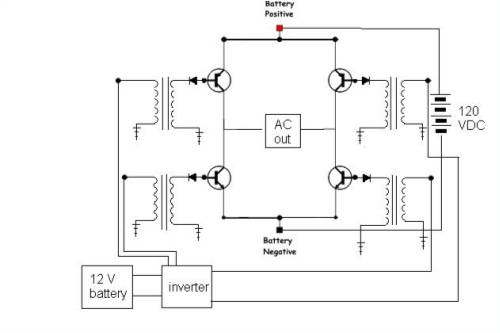
philb |
| |
oztules
Guru
Joined: 26/07/2007
Location: AustraliaPosts: 1686 |
| Posted: 01:00am 20 Jul 2008 |
Copy link to clipboard |
Print this post |
|
Good start, but no. The transformers need to be synched, the diodes can go, the trannies are wrong, but the concept is good.
gotto do some work, people arrived just now
Will get back to this soon
........oztules
Village idiot...or... just another hack out of his depth |
| |
Robb
Senior Member

Joined: 01/08/2007
Location: AustraliaPosts: 221 |
| Posted: 02:30am 20 Jul 2008 |
Copy link to clipboard |
Print this post |
|
Most of the cheapy modified sinewave inverters you buy use a somewhat simalar method.
It goes something like this:
12 volt in ----> inverter operating at 40Khz or there abouts -----> high voltage DC out ------> H bridge -----> modified sine wave.

You can see the 4 "H bridge" mosfets in this inverter next to the secondary filter capacitor with the sticker on top.
I'm thinking a modified inverter with HV DC input.......Edited by Robb 2008-07-21 |
| |
oztules
Guru
Joined: 26/07/2007
Location: AustraliaPosts: 1686 |
| Posted: 02:58am 20 Jul 2008 |
Copy link to clipboard |
Print this post |
|
Yes Robb is correct, and that I had previously envisioned this arrangement. However, a multi-kilowatt inverter is expensive.
The el cheapo inverter is only to supply a steady referenced 60hz with an appropriate waveform. This saves us designing that whole part. We now only have to switch our supplied hv dc. The elcheapo will also provide a low impedance driver.
For my first go I would use something like this Philb:
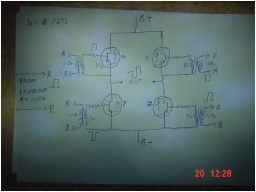
It should be that simple to get it going. Note that 2 of the driver transformers are inverted from the other two.
This means a positive going waveform will turn on two of the fets, while reverse biasing the other two. When the wave front changes, the opposite happens. It's apparently that simple. I can't recall if Fanman used fets or igbt's.
But 200A 1200v IBGT's should get you on track I suspect.
Perhaps see if you can get hold of Fanman.
If you have just square wave 115vdc may do, if you have modified sine, perhaps closer to 160v dc. You can find this out by measuring the hvdc in the converter itself and trying that voltage.
I must admit, it does look simple
..........oztules
Village idiot...or... just another hack out of his depth |
| |
Robb
Senior Member
Joined: 01/08/2007
Location: AustraliaPosts: 221 |
| Posted: 03:10am 20 Jul 2008 |
Copy link to clipboard |
Print this post |
|
Not sure I'd just drive them with transformers. You realy want to switch them clean and sharp or else your going to be disipating loads of power and let the smoke out .
You'd at least need something like Schmitt triggers to square it all up.
Now if you want pure sine wave it all gets a lot more complicated........Edited by Robb 2008-07-21 |
| |
oztules
Guru
Joined: 26/07/2007
Location: AustraliaPosts: 1686 |
| Posted: 03:37am 20 Jul 2008 |
Copy link to clipboard |
Print this post |
|
Robb ,
We are switching at only 60hz. The turn on time versus the on time is quite stark. They spend very little time turning on as a percent of the cycle.
At this frequency we are clean and sharp.
For pure sine, I think d class would be the best, but not needed for this.
Here I have found Fanmans description:
"fanman dave here, .......... i bought a radioshack 75 watt msw inverter and used it for the wave signal, that goes to four radioshack 300 milliamp 12 volt to 120 volt transformers, that circuit controls the on off signals, then the 12 volt output goes to 8 mosfets 4 in parallel that turn on for the positive half cycle and 4 that come on for the negative half cycle. and yes it all goes through a full bridge circuit. it really does work really good and guite efficintly i measure only about 4 watts idol current, it has no overcurrent protection, or no voltage regulation, so it fluctuates with voltage, but ive never had any prblems in that regards. my batteries are 120 volt so straight in and straight out, uasuly it comes out about 130 i figure thats from the rms value, im not sure. when lightning strikes all i have to do is replace the mosfets, its really easy."
Says it all really.
He mentions in a previous post he is running 5kw. So if we are to believe him..... it works.
So Philb, I think he is in Michigan now, maybe you can track him down.
........oztulesEdited by oztules 2008-07-21
Village idiot...or... just another hack out of his depth |
| |
oztules
Guru
Joined: 26/07/2007
Location: AustraliaPosts: 1686 |
| Posted: 04:39am 20 Jul 2008 |
Copy link to clipboard |
Print this post |
|
Robb,
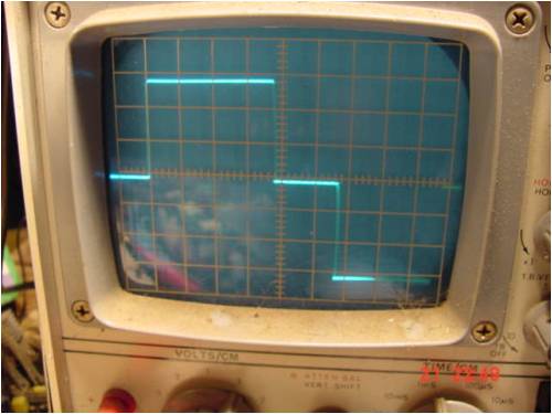
You got me thinking so I went out to the shed and mocked up an old inverter I had, a small transformer and my mouldy old CRO.
It surprised even me. My scope performs really really badly at low frequency, and is difficult to photo as it blinks at low freq. However, I was able to stretch the half wave so we could see how fast the rise time was compared to plateau.
It is much quicker than even I thought
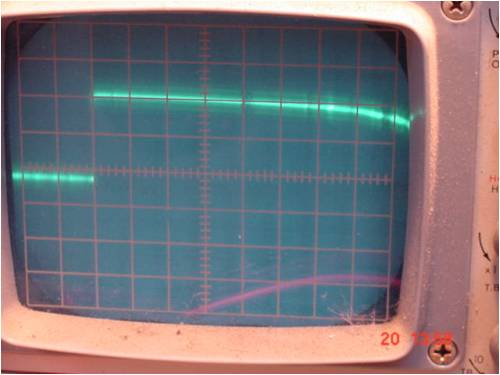
The trailing edge of the wave falls off, but still over 12v, then drops like a rock as well.
Looks like a zener or two might be all thats needed to clip the waveform , peel off the superimposed switching noise, have a very fast wave front, and protect the gate from too much drive. This is 10v/division. Plenty left to clip.
This was from this (pictured) converter through a little 14v? transformer. I expected some hysterisis to show up, but it is not obvious.
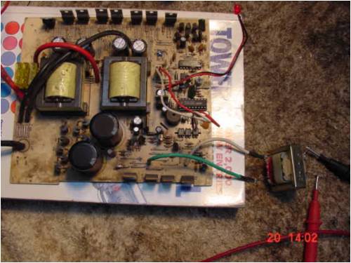
I don't think we need the schmitt triggers, just a clipper.
Thanks for making me look at it.
.........oztulesEdited by oztules 2008-07-21
Village idiot...or... just another hack out of his depth |
| |
oztules
Guru
Joined: 26/07/2007
Location: AustraliaPosts: 1686 |
| Posted: 11:55am 21 Jul 2008 |
Copy link to clipboard |
Print this post |
|
Inverters,inverters, inverters.......
Robb,
I had found this at the tip some time ago, and for no apparent reason decided to fix it today
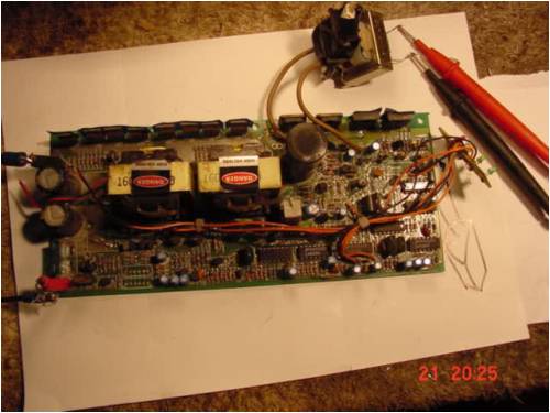
The fault was in the high side driver transistor and a few other components and 2 of the H bridge fets... so what I hear you say....
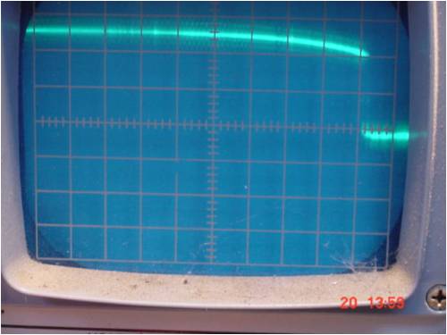
well on getting it going, I decided to try the scope on the output with the transformer like yesterday...oops.
look at this:
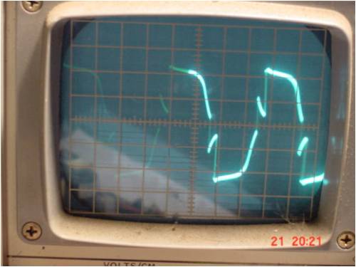
So it would appear that in this case you are right. A schmitt to shape the wave may be in order in this case.
It is an older American one, analogue not micro, soft start etc etc. about 1000w. This picture is of it running the light, as it needed a load to run. It had auto sensing as well.
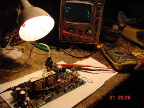
So not all inverters are created equal. Note the scope in the last picture, it was in the dark part of the blink. These old cro's are not so good at low freq.
..........oztules
Edited by oztules 2008-07-22
Village idiot...or... just another hack out of his depth |
| |
oztules
Guru
Joined: 26/07/2007
Location: AustraliaPosts: 1686 |
| Posted: 01:48pm 21 Jul 2008 |
Copy link to clipboard |
Print this post |
|
Damn, 
The transformer was at fault. I measured the output on the scope at the 240v primary side with a 90k voltage divider across the 240v. 50v/division and it looked like this:
Then replaced the transformer with another and scoped the secondary 10v/division... and it looked like this :
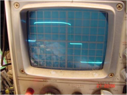
So we don't need the schmitts yet from the looks of it. There is some small drop off but not enough to give any problem at all. Don't understand how it is so different. The tiny transformer skewed the result awfully. The slightly larger one worked beautifully. I've run pwm dc controllers with worse waveforms than that.
Perhaps next time I will test it a bit more thoroughly 
Village idiot...or... just another hack out of his depth |
| |
philb
Regular Member
Joined: 05/07/2008
Location: United StatesPosts: 96 |
| Posted: 02:15pm 21 Jul 2008 |
Copy link to clipboard |
Print this post |
|
Thanks oztules for all the work in answering my questions and for Robb's input to get curiosity sturred up.
BTW, I reread all Fanman's posts and I cannot find hide nor hair of him.
In the meantime, I'm gathering materials.
I have 8 of GA200SA60V-nd from Digikey. They are N-channel 100A 600V IGBT's. Here is the sheet. http://www.vishay.com/docs/93630/93630ga2.pdf
Also, some transformers from 600 watt APC UPS's. They are 12:120 Volt units.
It may take me a while to get going. Hot water heater and washer went out last week end. I'm running low on baling wire and duck tape. The supervisor is watching the repairs. 
philb |
| |
| |
Page 1 of 2 |
