
|
|
Forum Index : Electronics : Basic Dumb Mosfet Question.
| Author | Message | ||||
| Davo99 Guru Joined: 03/06/2019 Location: AustraliaPosts: 1585 |
I have spent ( too much) time looking on the net but can't find an answer to a basic Question. Are Mosfets ( one type or the other) like conventional relays where you can use a low input current to switch a Much Higher one? I thought that was their basic premise but mucking around with some I pulled out of an old GTI, all the legs seem to draw roughly the same power which doesn't make sense to me. Maybe I'm using the wrong Fets or they are stuffed or it's just the way they work. Knowing if My expectations are correct or not will be the first thing in determining if I am going about things the wrong way to start. Thanks for any education of the dummies. |
||||
mackoffgrid Guru Joined: 13/03/2017 Location: AustraliaPosts: 460 |
That statement better describes a conventional Transistor, NPN or PNP. The physics of Mosfets is even more weird but, simply - you apply a voltage to the gate and that voltage will determine the resistance of the Drain to Source path. Unusually, 10v is enough to lower the resistance to its minimum amount which is referred to as Rds. One of the favourite Mosfets among the Ozinverters is the HY4008 and it has a Rds of 2.9 milli ohms. BTW, If you simply apply a static DC voltage to the Gate, it will consume negligible power. Cheers Andrew |
||||
| Poppy Guru Joined: 25/07/2019 Location: GermanyPosts: 486 |
A little quotation from Charles Platt Encyclopedia of Electronic Components Volume 1 O�Reilly, 2013 Actually you can use both as simple switches and if they are "power" versions then comparable to a simple relay, but generally without galvanic isolation.  Edited 2019-08-06 16:59 by Poppy Andre ... such a GURU? | ||||
| Davo99 Guru Joined: 03/06/2019 Location: AustraliaPosts: 1585 |
Thank you Andrew. I am putting power on the gate and it's sucking a lot of power. Least I know that's not the way it should be and can try and find what I am doing wrong. Would it be in the ball park to say a mosfet can be like a variable resistor depending on the voltage applied to the gate as far as the amount of power that will pass between the source and the drain? Thanks again. |
||||
| Davo99 Guru Joined: 03/06/2019 Location: AustraliaPosts: 1585 |
Thanks Poppy. Enlightens me a bit too. |
||||
| Poppy Guru Joined: 25/07/2019 Location: GermanyPosts: 486 |
What component is it exactly? Andre ... such a GURU? | ||||
| poida Guru Joined: 02/02/2017 Location: AustraliaPosts: 1480 |
Oh yes, for sure. I built a constant current DC load using some special mosfets. I can control the current the device consumes with a potentiomer from zero to about 8 Amps, and with voltages from about 4V to 50V. 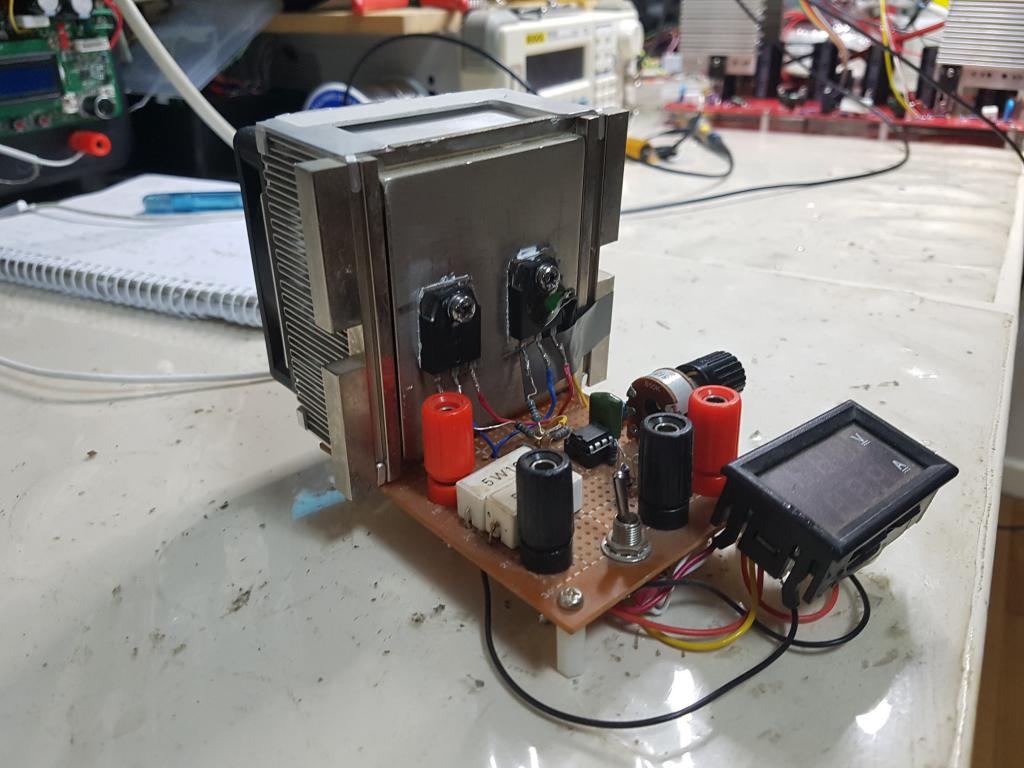 Some MOSFETs are very good switches and others are more useful when used in the intermediate gate drive voltages, becoming the variable resistor. The constant current device of mine is the latter. In posts here on the forum I explored how easy it was to destroy the switching optimised type MOSFETS by running them so that they are partly switched on. The HY4008 was very easy to kill in these tests. The constant current thing I made uses NEC K3304 MOSFETS which are quite happy to run at any gate voltage, producing large amounts of heat. I drive the gates via an op-amp output such that the op-amp ensures the voltage drop across the large resistors equals the voltage out of the potentiometer. This way I have a current control. (this device has been invaluable in helping me understand switching power supplies and inverter theory) In the application of inverters and power conversion & control in general, MOSFETS are always driven in such a way as to ensure they are either full ON or full OFF and to take as little time as possible when changing states. When OFF the MOSFET consumes zero energy and when fully ON it also consumes timy amounts of energy. It's the time spent going from one to the other state where most of the heat is generated. wronger than a phone book full of wrong phone numbers |
||||
| mackoffgrid Guru Joined: 13/03/2017 Location: AustraliaPosts: 460 |
Peter, Would you mind posting a schematic (sketch) of your circuit. Cheers Andrew |
||||
| Warpspeed Guru Joined: 09/08/2007 Location: AustraliaPosts: 4406 |
|
||||
| poida Guru Joined: 02/02/2017 Location: AustraliaPosts: 1480 |
Mack: two DC terminal pairs, one for 12V supply, one for the DC load. I use the LM358 as a comparator to control the cooling fan. And place the NTC on the heatsink, I put it on the top of one of the FETS This is from memory. Probably only need 50R gate resistors, maybe a 100nF cap. The power FETS are tricky. You can not use the usual power MOSFET such as HY4008. They will be weak, and blow ever so quietly under low loads. (about 1/5 of what you expect from the spec's safe operating area. The NEC K3304 I salvaged from a dead plasma TV or something are very good for this. No idea what else to use. IGBTs were suggested. I have had 150W continuous on this thing, peaks of 200W 10A at 20V is reasonable, 5A at 30V all day. 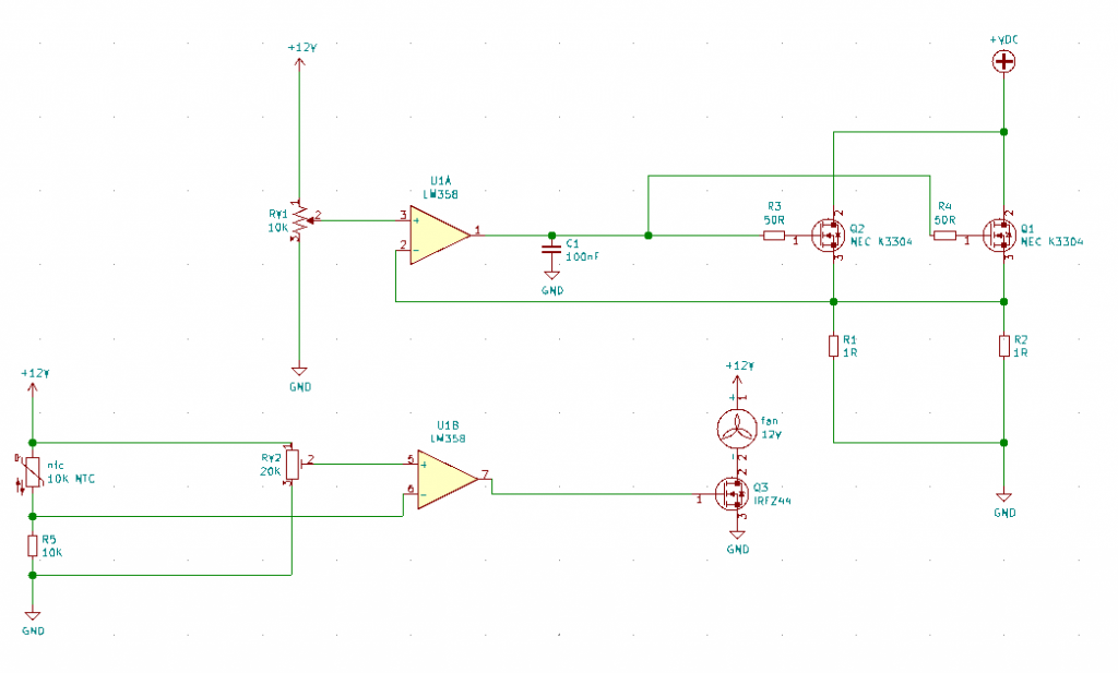 wronger than a phone book full of wrong phone numbers |
||||
| mackoffgrid Guru Joined: 13/03/2017 Location: AustraliaPosts: 460 |
Thanks I was going to use standard Power Mosfet but I'll be more careful now IGBT makes good sense.Cheers Andrew |
||||
| poida Guru Joined: 02/02/2017 Location: AustraliaPosts: 1480 |
and the 100nF cap is probably not needed. But have a go and see what happens. The feeling of Absolute Power when you twiddle the pot's knob to go from 0.5A to 5A, just like that, is intoxicating. I'd love to figure out some sort of variable load for 240V AC, from 0 to 5kW again controlled by a pot. I want to test the inverters. I wonder if a large salt water bath, with 2 large plates, connected to a 3kW Areosharp toroid via a low voltage secondary might work. Have a motor dip in more or less under some control mechanism.. wronger than a phone book full of wrong phone numbers |
||||
| The Back Shed's forum code is written, and hosted, in Australia. | © JAQ Software 2026 |
